Content .. 1057 1058 1059 1060 ..
Mitsubishi Galant (2004+). Manual - part 1059
MULTIPORT FUEL INJECTION (MFI) DIAGNOSIS
TSB Revision
MULTIPORT FUEL INJECTION (MFI) <2.4L ENGINE>
13A-1053
.
AK303936
B-101 (GR)
B-102 (GR) B-117 (GR)
B-118 (GR)
AB
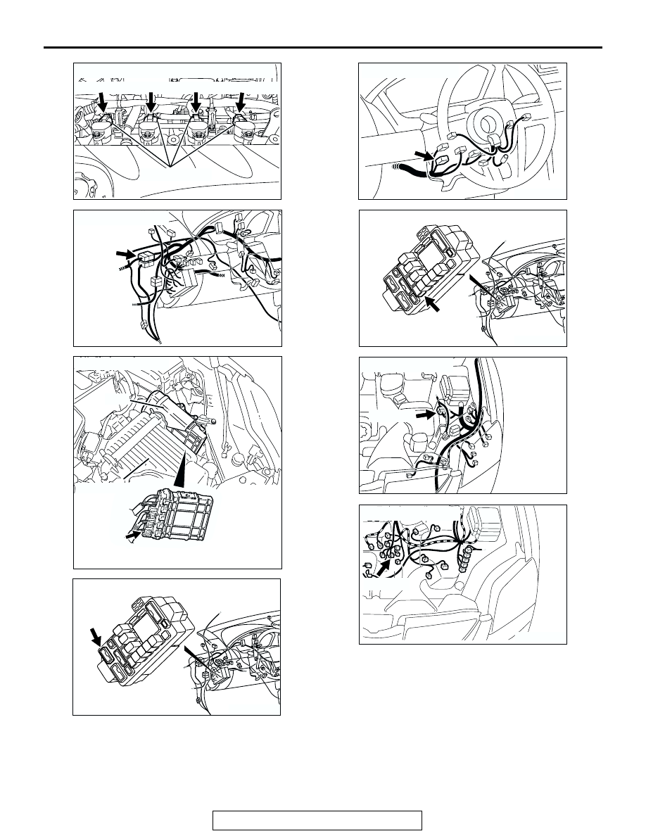
CONNECTORS: B-101, B-102, B-117, B-118
IGNITION COIL
AK303918AB
C-29
CONNECTOR: C-29
AK303059
CONNECTOR: B-23
PCM
AB
AIR CLEANER
B-23
AK303925AB
CONNECTOR: C-215
C-215
AK303923AB
CONNECTOR: C-308
C-308
AK303915AB
CONNECTOR: C-211
C-211
AK303872AB
A-13 (GR)
CONNECTOR: A-13
AK303937 AB
CONNECTOR: B-111
B-111 (B)