Mitsubishi Galant. Manual - part 721


  Index      Mitsubishi     Mitsubishi Galant - service repair manual 2001 year


Search            


Content   ..  719  720  721  722   ..


Mitsubishi Galant. Manual - part 721


MANUAL A/C DIAGNOSIS

TSB Revision

HEATING AND AIR CONDITIONING

55-10

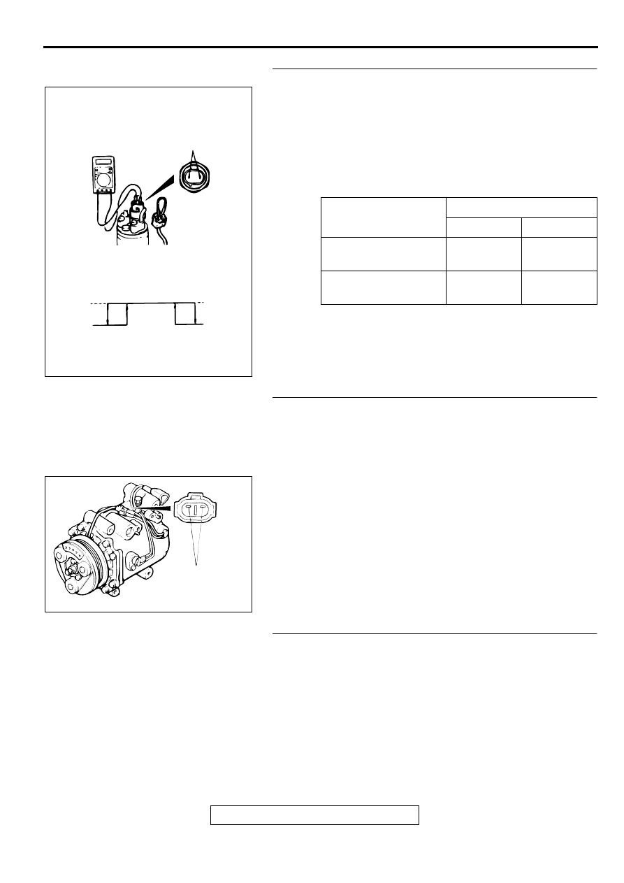
STEP 2. Check the dual pressure switch operation.
(1) Remove the dual pressure switch connector and connect 

the high/low pressure side terminals located on the harness 
side as shown in the illustration.

(2)  Install a gauge manifold to the high-pressure side service 

valve of the refrigerant line. (Refer to 

P.55-22

.)

(3) When the high/low pressure sides of the dual pressure 

switch are at operation pressure (ON) and there is 
continuity between the respective terminals.

Q: When the high/low pressure sides of the dual pressure 

switch are at operation pressure (ON), is there 
continuity between the respective terminals?
YES : 
Go to Step 3.
NO :  Replace the switch. Then go to Step 6.

STEP 3. Check the refrigerant-temperature switch 
operation.

Q: When the A/C is off, check that there is continuity 

between the refrigerant-temperature switch terminals. Is 
the circuit open loop?
YES : 
Replace the switch. Then go to Step 6.
NO :  If less than two ohm, go to Step 4.

STEP 4. Measure the automatic compressor controller 
terminal voltage.
Refer to 

P.55-17

.

Q: Is the automatic compressor controller terminal voltage 

in good condition?
YES : 
Go to Step 5.
NO :  Replace. Then go to Step 6.

ITEMS

SWITCH POSITION

OFF 

 ON

ON 

 OFF

Low-pressure side kPa 
(psi)

221 (32.1)

196 (28.4)

High-pressure side 
kPa (psi

2,354 (341.4) 2,942 (426.7)

A003021

HIGH/LOW
PRESSURE SIDE

LOW-PRESSURE
SIDE

HIGH-PRESSURE
SIDE

ON

OFF

ON

OFF

AB

AC001372

REFRIGERANT
TEMPERATURE
SWITCH TERMINALS

AB

MANUAL A/C DIAGNOSIS

TSB Revision

HEATING AND AIR CONDITIONING

55-11

STEP 5. Measure the engine control module <M/T>/the 
powertrain control module <A/T> terminal voltage.
(1) Refer to GROUP 13A, Diagnosis 

 Check at The Engine 

Control Module (ECM) <M/T> or Powertrain Control Module 
(PCM) <A/T> <2.4L engine>

P.13A-417

(2) Refer to GROUP 13B, Diagnosis 

 Check at The 

Powertrain Control Module (PCM) <A/T> <3.0L 
engine>

P.13A-417

Q: Is the voltage in good condition?

YES : Go to Step 6.
NO :  Replace. Then go to Step 6.

STEP 6. Check symptoms.

Q: Is the cool air discharged?

YES : This diagnosis is complete. (If no malfunctions are not 

found in all steps, an intermittent malfunction is 
suspected. Refer to Introduction, How to Use 
Troubleshooting/Inspection Service Points 

 How to 

Cope with Intermittent Malfunction 

P.00-8

.)

NO :  Go to Step 1.

INSPECTION PROCEDURE 4: BLOWER FAN AND MOTOR DOES NOT TURN.

DIAGNOSIS

STEP 1. Check the blower relay continuity.

Q: Is the blower relay continuity in good condition?

YES : Go to Step 2.
NO :  Replace. Then go to Step 5.

BATTERY 
VOLTAGE

TERMINAL NO. 
TO BE 
CONNECTED TO 
BATTERY 

TERMINAL NO. 
TO BE 
CONDUCTED

SUPPLIED

1-3

2-5

NOT SUPPLIED

-

1-3

AC003706 AB

BLOWER RELAY

MANUAL A/C DIAGNOSIS

TSB Revision

HEATING AND AIR CONDITIONING

55-12

STEP 2. Check the blower fan and motor operation.
When battery voltage is applied between the terminals, check 
that the motor operates.

Q: Is there any abnormal noise?

YES : Go to Step 3.
NO :  Replace. Then go to Step 5.

STEP 3. Check the blower switch continuity.

Q: Is the blower switch continuity in good condition?

YES : Go to Step 4.
NO :  Replace. Then go to Step 5.

STEP 4. Check the resistor resistance value.
Use an ohmmeter to measure the resistance between the 
terminals as indicated below. Check that the measured value is 
at the standard value.

Standard value:

Q: Is the measured value at the standard value?

YES : Go to Step 5.
NO :  Replace. Then go to Step 5.

AC001377AB

SWITCH 
POSITION

TESTER 
CONNECTION
(CONNECTOR A) 

SPECIFIED 
CONDITION

0 (OFF)

-

No continuity

1 (LO)

3-5

Continuity

2 (ML)

1-3

Continuity

3 (MH)

3-6

Continuity

4 (HI)

3-4

Continuity

AC001371

BLOWER SWITCH
ASSEMBLY

AB

MEASUREMENT TERMINAL

STANDARD VALUE 

Between terminals 3 and 2 (LO)

2.3

Between terminals 3 and 4 (ML)

1.1

Between terminals 3 and 1 (MH)

0.4

AC001379AB

MANUAL A/C DIAGNOSIS

TSB Revision

HEATING AND AIR CONDITIONING

55-13

STEP 5. Check symptoms.

Q: Is the blower fan and motor turned?

YES : This diagnosis is complete. (If no malfunctions are not 

found in all steps, an intermittent malfunction is 
suspected. Refer to Introduction, How to Use 
Troubleshooting/Inspection Service Points 

 How to 

Cope with Intermittent Malfunction 

P.00-8

.)

NO :  Go to Step 1.

INSPECTION PROCEDURE 5: BLOWER FAN AND MOTOR DOES NOT STOP TURNING.

DIAGNOSIS

STEP 1. Check the harness wire between the blower fan 
and motor connector C-11, the resistor connector C-14, 
and the blower switch connector C-53.

Q: Is the harness wire between the blower fan and motor 

connector C-11, the resistor connector C-14, and the 
blower switch connector C-53 in good condition?
YES : 
Go to Step 2.
NO :  Repair it. Then go to Step 4.

AC003733

CONNECTORS: C-11, C-14, C-53

AB

C-11

C-14

C-53


Content   ..  719  720  721  722   ..