Mitsubishi Galant. Manual - part 717


  Index      Mitsubishi     Mitsubishi Galant - service repair manual 2001 year


Search            


Content   ..  715  716  717  718   ..


Mitsubishi Galant. Manual - part 717


SWS DIAGNOSIS

TSB Revision

SIMPLIFIED WIRING SYSTEM (SWS)

54B-263

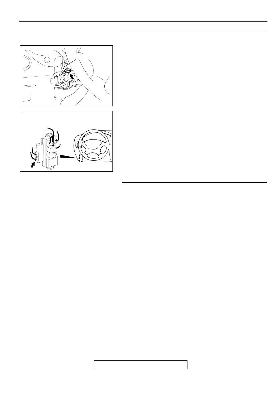
STEP 3. Check the harness wire between column switch 
connector C-60 and ETACS-ECU connector C-82.
Q: Is the harness wire between column switch connector 

C-60 and ETACS-ECU connector C-82 in good 
condition?
YES : 
Go to 4.
NO :  Repair it. Check that the input signal from the 

windshield intermittent wiper interval adjusting knob 
can be checked and the wiper interval can be 
adjusted.

STEP 4. Replacement of ECU
(1)Replace the ETACS-ECU.
(2) Check that the input signal from the windshield intermittent 

wiper interval adjusting knob can be checked and the wiper 
interval can be adjusted.

Q: Is the input signal from the windshield intermittent 

wiper interval adjusting knob input normally?
YES : 
There is no action to be taken.
NO :  Replace the column switch. Check that the input 

signal from the windshield intermittent wiper interval 
adjusting knob can be checked and the wiper interval 
can be adjusted.

AC003078 AB

CONNECTOR: C-60

COLUMN SWITCH

AC003082AC

JUNCTION BLOCK
(FRONT VIEW)

CONNECTOR: C-82

SWS DIAGNOSIS

TSB Revision

SIMPLIFIED WIRING SYSTEM (SWS)

54B-264

Inspection Procedure N-17: Transmitter: The lock, unlock, trunk or panic switch singal is not sent to 
the ETACS-ECU.

CIRCUIT OPERATION
The ETACS-ECU receives an input signal from the 
transmitter through its built-in receiver, and evaluates 
the signal to operate various functions.

TECHNICAL DESCRIPTION (COMMENT)
The transmitter input signal is used to operate the 
following systems:

Keyless entry system

Theft-alarm system <vehicles with theft-alarm 
system>

If the signal fails, these systems will not work 
normally.

TROUBLESHOOTING HINTS

Malfunction of the transmitter

Malfunction of the ETACS-ECU

STEP 1. Register the transmitter.
Register the transmitter (Refer to GROUP 42, Keyless Entry 
System 

 On-vehicle Service 

 How To Secret  Registration 

Method 

P.42-70

.)

Q: Is the transmitter registered successfully?

YES : The transmitter input signal should be able to be 

checked and the functions, which are described in the 
"Technical Description (comment)," should work 
normally.

NO :  Go to Step 2.

STEP 2. Check the transmitter battery.
Measure the transmitter battery's voltage.

Q: Is the voltage approximately 2.5 

−−−−

 3.2 volts?

YES : Go to Step 3.
NO :  Replace the battery. If the transmitter is registered 

successfully, the transmitter input signal should be 
able to be checked and the functions, which are 
described in the "Technical Description (comment)," 
should work normally.

AC004205

Receiver and Transmitter Communication System

ACX01609

SWS DIAGNOSIS

TSB Revision

SIMPLIFIED WIRING SYSTEM (SWS)

54B-265

STEP 3. Check the transmitter.
(1)Use an other transmitter to register the secret code. (Refer 

to GROUP 42, Keyless Entry System 

 On-vehicle Service 

 How To Secret  Registration Method 

P.42-70

 .)

Q: Is the transmitter registered successfully?

YES : The transmitter input signal should be able to be 

checked and the functions, which are described in the 
"Technical Description (comment)," should work 
normally.

NO :  Replace the ETACS-ECU. The transmitter input 

signal should be able to be checked and the 
functions, which are described in the "Technical 
Description (comment)," should work normally.

Inspection Procedure O-1: Check the circuit (power supply line) from the battery to the ETACS-ECU.

CHECK THE CIRCUIT (POWER SUPPLY LINE) FROM BATTERY

Refer to Inspection Procedure A-1 (

P.54B-31

).

CIRCUIT OPERATION
The ETACS-ECU is always energized by the battery.

TECHNICAL DESCRIPTION (COMMENT)
If that power supply circuit is defective, the circuit 
flowing through the ignition switch (IG1) will function 
as a backup circuit. In this case, the following 
functions will not work when the ignition switch is at 
"LOCK" (OFF) position:

Ignition key reminder tone alarm function

Light reminder tone alarm function

Central door locking system

Hazard warning light

Dome light dimming function

Theft-alarm system <vehicles with theft-alarm 
system>

TROUBLESHOOTING HINTS

Malfunction of the ETACS-ECU

Damaged harness wires or connectors

DIAGNOSIS

Required Special Tools:

MB991223: Test Harness Set

MB991502: Scan Tool (MUT-II)

MB991529: Diagnostic Trouble Code Check Harness

STEP 1. Check the battery circuit at the ETACS-ECU 
connector C-86.
(1)Disconnect the ETACS-ECU connector C-86 and measure 

at the junction block side.

(2)Measure the Voltage between terminal 2 and ground.

Q: Is the voltage approximately 12 volts (battery positive 

voltage)?
YES : 
Replace the ETACS-ECU. The functions, which are 

described in the "Technical Description (comment)," 
should work normally.

NO :  Go to Step 2.

19

20

18 17 16 15 14 13 12 11 10 9

8

7

6

5

4

3

2

1

AC002181

CONNECTOR C-86
(JUNCTION BLOCK SIDE)

AB

SWS DIAGNOSIS

TSB Revision

SIMPLIFIED WIRING SYSTEM (SWS)

54B-266

STEP 2. Check ETACS-ECU connector C-86 for damage.
Q: Is ETACS-ECU connector C-86 in good condition?

YES : Go to Step 3.
NO :  Repair or replace it. Refer to GROUP 00E, Harness 

Connector Inspection 

P.00E-2

  . The functions, which 

are described in the "Technical Description 
(comment)," should work normally.

STEP 3. Check the harness wires between ETACS-ECU 
connector C-86 and battery.
NOTE: After checking junction block connector C-84 and 
intermediate connector C-66, check the wires. If junction block 
connector C-84 and intermediate connector C-66 are 
damaged, repair or replace them. Refer to GROUP 00E, 
Harness Connector Inspection 

P.00E-2

.

Q: Are the harness wires between ETACS-ECU connector 

C-86 and battery in good condition?
YES : 
There is no action to be taken.
NO :  Repair them. The functions, which are described in 

the "Technical Description (comment)," should work 
normally.

AC003080 AD

JUNCTION BLOCK
(REAR VIEW)

CONNECTOR: C-86

AC003080 AD

JUNCTION BLOCK
(REAR VIEW)

CONNECTOR: C-86

AC003079 AB

CONNECTOR
BLOCK (LH)

CONNECTOR: C-66

AC003080 AB

JUNCTION BLOCK
(REAR VIEW)

CONNECTOR: C-84


Content   ..  715  716  717  718   ..