Mitsubishi Galant. Manual - part 624


  Index      Mitsubishi     Mitsubishi Galant - service repair manual 2001 year


Search            


Content   ..  622  623  624  625   ..


Mitsubishi Galant. Manual - part 624


COMBINATION METERS ASSEMBLY AND VEHICLE SPEED SENSOR

TSB Revision

CHASSIS ELECTRICAL

54A-49

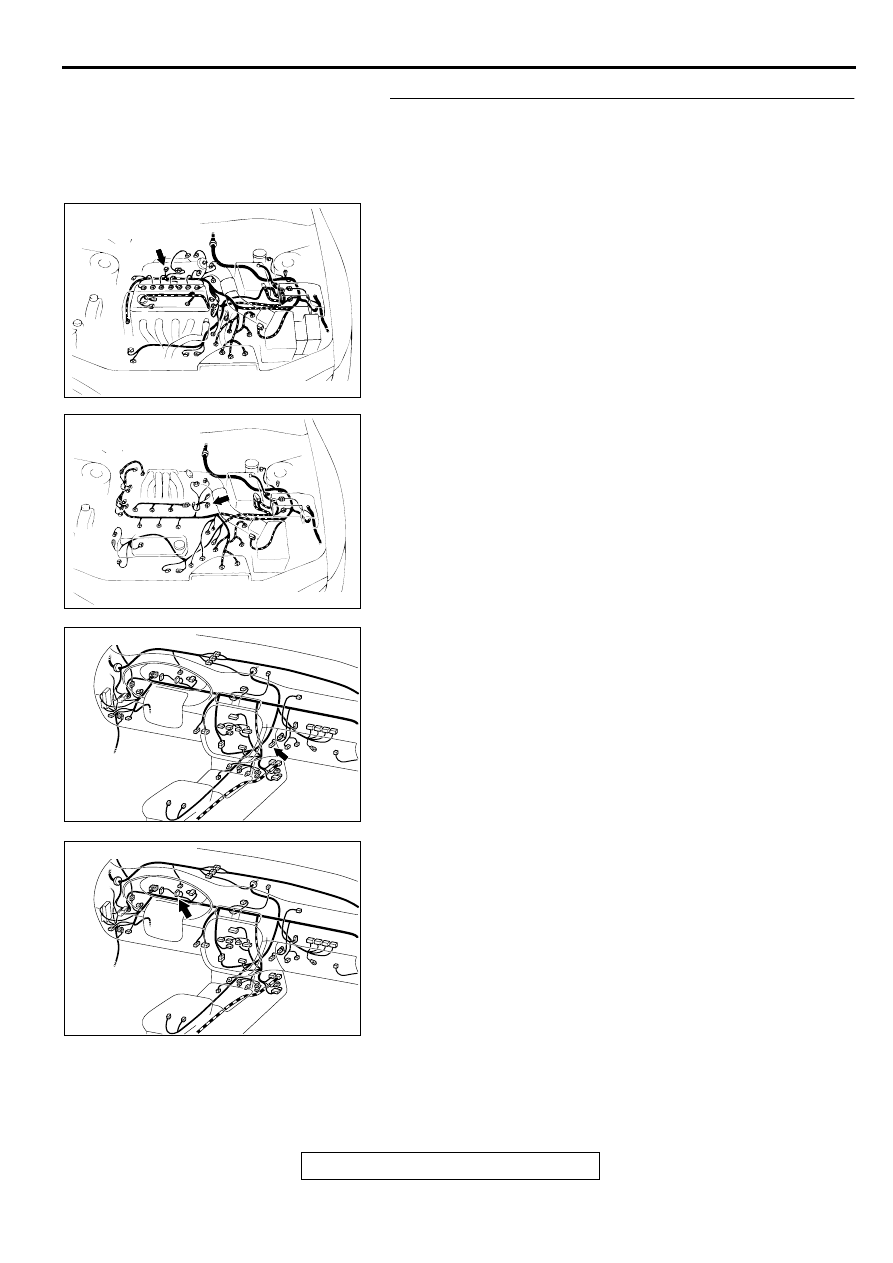
STEP 5. Check the harness wires from combination meter 
connector C-30 to ignition failure sensor connector B-01 
<2.4L engine>, distributor assembly connector B-27 <3.0L 
engine>, automatic compressor controller connector C-16 
<3.0L engine>.

AC003693AB

CONNECTOR: B-01
<2.4L ENGINE>

AC003694AB

CONNECTOR: B-27
<3.0L ENGINE>

AC003089

CONNECTOR: C-16

AS

AC003089 AH

CONNECTOR: C-30

TSB Revision

CHASSIS ELECTRICAL

COMBINATION METERS ASSEMBLY AND VEHICLE SPEED SENSOR

54A-50

NOTE:  After checking intermediate connector C-17,check the 
wires. If intermediate connector C-17 is damaged, repair or 
replace it. Refer to GROUP 00E, Harness Connector 
Inspection 

P.00E-2

.

Q: Is the harness wires from combination meter connector 

C-30 to ignition failure sensor connector B-01 <2.4L 
engine>, distributor assembly connector B-27 <3.0L 
engine>, automatic compressor controller connector C-
16 <3.0L engine> in good condition?
YES : 
There is no action to be taken.
NO :  Repair it. The tachometer should work normally.

AC003089 AI

CONNECTOR: C-17

COMBINATION METERS ASSEMBLY AND VEHICLE SPEED SENSOR

TSB Revision

CHASSIS ELECTRICAL

54A-51

Inspection Procedure 3: Fuel gauge does not work.

AC003972 AB

Fuel Gauge Circuit

TSB Revision

CHASSIS ELECTRICAL

COMBINATION METERS ASSEMBLY AND VEHICLE SPEED SENSOR

54A-52

CIRCUIT OPERATION

The ignition switch (IG1) circuit is the power 
source for the fuel gauge.

The resistance value fluctuates causing the 
circuit current to fluctuate when the fuel gauge 
unit the float moves up and down.

The fuel gauge moves the needle by the circuit 
current.

TECHNICAL DESCRIPTION (COMMENT)
If the ignition switch (IG1) circuit is open, the gauge 
needle will not move at all. If the ground circuit is 
open, the gauge needle will move up to its extreme 
position.

TROUBLESHOOTING

Malfunction of the fuel pump module (fuel gauge 
unit)

Malfunction of the combination meter (printed-
circuit board or fuel gauge assembly)

DIAGNOSIS

Required Special Tool:
MB991223: Harness Set

STEP 1. Check the speedometer operation.

Q: Does the speedometer work normally?

YES : Go to Step 2.
NO :  Refer to Inspection Procedure 1

P.54A-29

.

AC003089 AD

CONNECTOR: C-29

AC003082 AM

CONNECTORS: C-73, C-78

C-73

C-78

JUNCTION BLOCK
(FRONT VIEW)

AC003415 AC

CONNECTOR: C-71

CONNECTOR
BLOCK (RH)

AC001749AC

FUEL PUMP
MODULE

CONNECTOR: D-14


Content   ..  622  623  624  625   ..