Mitsubishi Galant. Manual - part 621


  Index      Mitsubishi     Mitsubishi Galant - service repair manual 2001 year


Search            


Content   ..  619  620  621  622   ..


Mitsubishi Galant. Manual - part 621


COMBINATION METERS ASSEMBLY AND VEHICLE SPEED SENSOR

TSB Revision

CHASSIS ELECTRICAL

54A-37

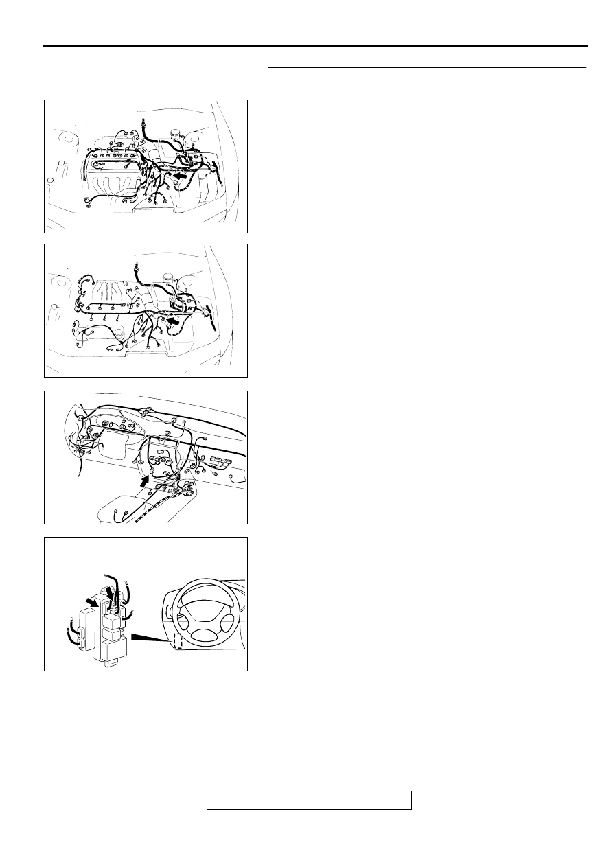
STEP 14. Check the harness wires between vehicle speed 
sensor connector B-35 and ignition switch (IG1).
NOTE: After checking junction block connectors C-73 and C-
74, intermediate connector C-17, check the wires. If junction 
block connectors C-73 and C-74, intermediate connector C-17 
are damaged, repair or replace them. Refer to GROUP 00E, 
Harness Connector Inspection 

P.00E-2

.

Q: Are the harness wires between vehicle speed sensor 

connector B-35 and ignition switch (IG1) in good 
condition?
YES : 
There is no action to be taken.
NO :  Repair them. The speedometer should work normally.

AC003686

CONNECTOR: B-35
<2.4L ENGINE>

AB

AC003687

CONNECTOR: B-35
<3.0L ENGINE>

AB

AC003089 AI

CONNECTOR: C-17

AC003082AW

CONNECTORS: C-73, C-74

C-73

JUNCTION BLOCK
(FRONT VIEW)

C-74

TSB Revision

CHASSIS ELECTRICAL

COMBINATION METERS ASSEMBLY AND VEHICLE SPEED SENSOR

54A-38

STEP 15. Check the vehicle speed sensor ground circuit at 
the vehicle speed sensor connector B-35.
(1) Disconnect the vehicle speed sensor connector B-35.
(2) Measure the resistance between terminal 2 and ground.

Q: Is the resistance less than 2 ohms?

YES : Go to Step 18.
NO :  Go to Step 16.

STEP 16. Check the vehicle speed sensor connector B-35 
for damage.
Q: Is vehicle speed connector B-35 in good condition?

YES : Go to Step 17.
NO :  Repair or replace it. Refer to GROUP 00E, Harness 

Connector Inspection 

P.00E-2

. The speedometer 

should work normally.

AC002751AB

CONNECTOR: B-35
(HARNESS SIDE)

AC003686

CONNECTOR: B-35
<2.4L ENGINE>

AB

AC003687

CONNECTOR: B-35
<3.0L ENGINE>

AB

COMBINATION METERS ASSEMBLY AND VEHICLE SPEED SENSOR

TSB Revision

CHASSIS ELECTRICAL

54A-39

STEP 17. Check the harness wire between vehicle speed 
sensor connector B-35 and ground.
Q: Is the harness wire between vehicle speed sensor 

connector B-35 and ground in good condition?
YES : 
There is no action to be taken.
NO :  Repair it. The speedometer should work normally.

STEP 18. Check the vehicle speed sensor signal circuit at 
the vehicle speed sensor connector B-35.
(1) Disconnect the vehicle speed sensor connector B-35.
(2) Turn the ignition switch to "ON"
(3) Measure the voltage between terminal 3 and ground.

Q: Is the voltage approximately 9 volts or more?

More than approximately 9 volts : Replace the vehicle 

speed sensor. The speedometer should work 
normally.

Approximately 9 volts : Go to Step 19 .

AC003686

CONNECTOR: B-35
<2.4L ENGINE>

AB

AC003687

CONNECTOR: B-35
<3.0L ENGINE>

AB

AC002749AB

CONNECTOR: B-35
(HARNESS SIDE)

TSB Revision

CHASSIS ELECTRICAL

COMBINATION METERS ASSEMBLY AND VEHICLE SPEED SENSOR

54A-40

STEP 19. Check the vehicle speed sensor connector B-35, 
radio and tape player connector C-31, auto-cruise control-
ECU connector C-52 <vehicles with auto-cruise control>, 
PCM connector C-41 and combination meter connector C-
30.

AC003686

CONNECTOR: B-35
<2.4L ENGINE>

AB

AC003687

CONNECTOR: B-35
<3.0L ENGINE>

AB

AC003089

C-31

CONNECTORS: C-30, C-31

AQ

C-30

AC003685

CONNECTOR: C-41

AC

PCM


Content   ..  619  620  621  622   ..