Mitsubishi Galant. Manual - part 608
AIR BAG MODULE(S) AND CLOCK SPRING
TSB Revision
SUPPLEMENTAL RESTRAINT SYSTEM(SRS)
52B-73
INSPECTION
M1524002500080
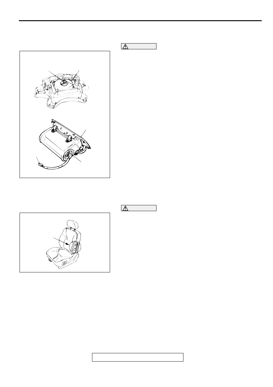
AIR BAG MODULE CHECK
WARNING
•
If any component damage is found during the
following inspection, replace the air bag module
with a new one. Dispose of the old one according
to the specified procedure. (Refer to
.)
•
Never attempt to measure the circuit resistance of
the air bag modules (squib) even if you are using
the specified tester. If the circuit resistance is
measured with a tester, accidental air bag
deployment will result in serious personal injury.
1. Check the pad cover for dents, cracks or deformation.
2. Check the connectors for damage, the terminals for
deformation, and the harness for binds.
3. Check the air bag inflator vase for dents, cracks or
deformation.
4. Install the air bag module (driver's side) to the steering
wheel and check fit and alignment with the wheel.
5. Install the air bag module (front passenger's side) to the
instrument panel and crossmember and check fit and
alignment.
6. Install the air bag module cover (front passenger's side) to
the instrument panel to check fit and alignment.
FRONT SEATBACK ASSEMBLY WITH SIDE AIR BAG
MODULE CHECK
WARNING
•
If any improper part is found during the following
inspection, replace the front seatback assembly
with a new one. Dispose of the old one according
to the specified procedure. (Refer to
.)
•
Never attempt to measure the circuit resistance of
the air bag module (squib) even if you are using
the specified tester. If the circuit resistance is
measured with a tester, accidental air bag
deployment will result in serious personal injury.
1. Check the air bag module deployment section for dents or
deformation.
2. Check connector for damage, terminals for deformation, and
harness for binds.
AC003214AB
<DRIVER'S SIDE>
<FRONT PASSENGER'S SIDE>
CONNECTOR
CONNECTOR
INFLATOR CASE
COVER
INFLATOR CASE
AC002988AB
AIR BAG MODULE
DEPLOYMENT
SECTION