Mitsubishi Galant. Manual - part 598


  Index      Mitsubishi     Mitsubishi Galant - service repair manual 2001 year


Search            


Content   ..  596  597  598  599   ..


Mitsubishi Galant. Manual - part 598


SRS AIR BAG DIAGNOSIS

TSB Revision

SUPPLEMENTAL RESTRAINT SYSTEM(SRS)

52B-33

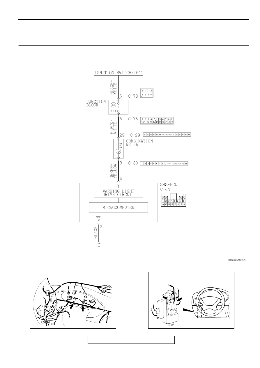
DTC 43: SRS warning light drive circuit system fault 1 (Light does not illuminate.)/SRS warning light 
drive circuit system fault 1 (Light does not switch off.)
DTC 44: SRS warning light drive circuit system fault 2

AC002980AB

SRS Warning Light Drive Circuit

AC003202AB

CONNECTOR: C-29, C-30

C-29

C-30

AC003203AB

CONNECTOR: C-73, C-78

JUNCTION BLOCK (FRONT)

C-73

C-78

SRS AIR BAG DIAGNOSIS

TSB Revision

SUPPLEMENTAL RESTRAINT SYSTEM(SRS)

52B-34

CIRCUIT OPERATION

Power for the SRS warning light is supplied from 
the ignition switch (IG1) circuit.

The SRS warning light illuminates when the 
ignition switch is turned "ON" and goes out after 
approximately 7 seconds if there is not a 
malfunction in the SRS system.

The SRS-ECU judges how severe a collision is 
by detecting signals from the left and right side 
impact sensors and the analog G-sensor. If the 
impact is over a predetermined level, the SRS-
ECU outputs an ignition signal. At this time, if the 
safing G-sensor is on, the SRS air bag will inflate.

DTC SET CONDITIONS

This DTC is output when an open circuit is 
detected for a continuous period of five seconds 
while the SRS-ECU is monitoring the SRS 
warning light and the light is OFF. (transistor 
OFF.) However, if the vehicle condition returns to 
normal, DTC 43 will be automatically erased, and 
the SRS warning light will go out.

This DTC is output when a short to ground occurs 
in the harness between the SRS warning light 
and SRS-ECU while SRS-ECU is monitoring the 
light and the light is ON. 

This DTC is output under one of the following 
cases while the SRS-ECU is monitoring the 
warning light drive circuit:

When a short circuit occurs in the warning 
light drive circuit.

When a malfunction is detected in the output 
transistor inside the SRS-ECU.

However, if the vehicle returns to normal 
condition, DTC 44 will be automatically erased, 
and the SRS warning light will go out.

TROUBLESHOOTING HINTS

Damaged wiring harnesses of connectors

Blown bulb (for DTC 43)

Malfunction of the SRS-ECU

Malfunction of the combination meter (for DTC 
43)

DIAGNOSIS

STEP 1. Check the SRS warning light line at SRS-ECU 
connector C-44 by backprobing.
(1)Do disconnect the connector C-44.
(2)Connect the negative battery cable.
(3)Turn the ignition switch to "ON" position.
(4)Connect terminal 4 to ground by backprobing.

The SRS warning light should illuminate.

Q: Does the SRS warning light illuminate?

YES : Replace the SRS-ECU. Refer to 

P.52B-65

Then go 

to Step 6.

NO :  Go to Step 2.

AC003195AB

CONNECTOR: C-44

SRS-ECU

CENTER
REINFORCEMENT

AC000372AD

C-44 CONNECTOR HARNESS VIEW

SRS AIR BAG DIAGNOSIS

TSB Revision

SUPPLEMENTAL RESTRAINT SYSTEM(SRS)

52B-35

STEP 2. Check the SRS warning light bulb.
Q: Has the SRS warning light bulb blown?

YES : Replace the SRS warning light bulb. Then go to Step 

6.

NO :  Go to Step 3.

STEP 3. Check the harness wires between the ignition 
switch (IG1) and SRS-ECU connector C-44.
NOTE: After inspecting intermediate connectors C-29, C-30, C-
73, C-78 inspect the wiring harness. If intermediate connectors 
C-29, C-30, C-73, C-78 are damaged, repair or replace them. 
Refer to GROUP 00E, Harness Connector Inspection 

P.00E-2

Then go to Step 6.

Q: Are the harness wires between the ignition switch (IG1) 

and SRS-ECU connector C-44 in good condition?
YES : 
Go to Step 4.
NO :  Repair them. Then go to Step 6.

AC003204AB

SRS WARNING LIGHT

AC003195AB

CONNECTOR: C-44

SRS-ECU

CENTER
REINFORCEMENT

AC003202AB

CONNECTOR: C-29, C-30

C-29

C-30

AC003203AB

CONNECTOR: C-73, C-78

JUNCTION BLOCK (FRONT)

C-73

C-78

SRS AIR BAG DIAGNOSIS

TSB Revision

SUPPLEMENTAL RESTRAINT SYSTEM(SRS)

52B-36

STEP 4. Check the ground line at the SRS-ECU connector 
C-44 by backprobing.
(1)Do disconnect the connector C-44.
(2)Measure the resistance between terminal 3 and ground by 

backprobing.

Should be less than 2 ohm.

Q: Is the resistance between terminal 3 and ground less 

than 2 ohm?
YES : 
Go to Step 6.
NO :  Go to Step 5.

STEP 5. Check the harness wires between SRS-ECU 
connector C-44 and ground.
Q: Are the harness wires between SRS-ECU connector C-

44 and ground in good condition?
YES : 
Go to Step 6.
NO :  Repair them. Then go to Step 6.

STEP 6. Check for DTC.

Q: Is any of DTC 43 or 44 output?

YES : There is no action to be taken.
NO :  This diagnosis is compleate.(If no malfunctions are 

not found in all steps, an intermittent malfunction is 
suspected. Refer to GROUP 00, How to Use 
Troubleshooting/Inspection Service Points 

 How to 

Cope with Intermittent Malfunction.) 

AC000368AD

C-44 CONNECTOR HARNESS SIDE VIEW

AC003195AB

CONNECTOR: C-44

SRS-ECU

CENTER
REINFORCEMENT


Content   ..  596  597  598  599   ..