Mitsubishi Galant. Manual - part 572


  Index      Mitsubishi     Mitsubishi Galant - service repair manual 2001 year


Search            


Content   ..  570  571  572  573   ..


Mitsubishi Galant. Manual - part 572


KEYLESS ENTRY SYSTEM

TSB Revision

BODY

42-71

If it appears that a problem is occurring because of faulty 
registration of a code.

A maximum of four different codes can be stored in the 
EEPROM memory (four different transmitters can be used). 
When the code for the first transmitter is registered, the 
previously registered codes for all transmitters are cleared. 
Therefore, if you are using four transmitters or are adding more 
transmitters, the codes for all transmitters must be registered at 
the same time.
1. Check that the doors lock normally when the key is used.

2. Insert the ignition key.

CAUTION

To prevent damage to scan tool MB991502, always turn the 
ignition switch to "LOCK" (OFF) position before 
connecting or disconnecting scan tool MB991502. 

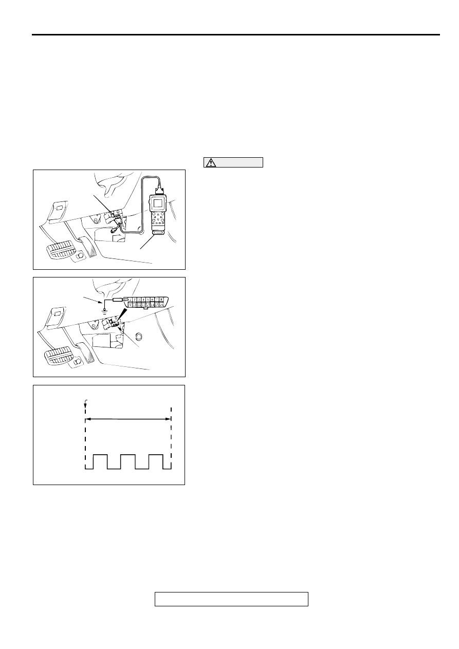
3. Connect the scan tool to the data link connector. If the scan 

tool is not used, ground terminal (1) of the data link 
connector.

NOTE: This will connect terminal (1) of the data link 
connector to ground, and the system will be in secret code 
registration standby mode.

4. Press the hazard switch six times within 10 seconds.

NOTE: At this time the code registration monitor request is 
output (all doors locked and unlocked) and becomes 
registration mode.

NOTE: The hazard warning light switch is turned on and off 
alternately whenever it is pushed.

5. Press the transmitter switch, and then press it two times 

within 10 seconds of the first press. This will register the 
code.

6. When registration is completed, the code registration 

monitor request is output (all doors locked and unlocked).

7. If you are using two or more transmitters or have added a 

second transmitter, the same registration procedure should 
be carried out within one minute after registering the code 
for the first transmitter. After the second registration is 
completed, the code registration monitor request is output 
(all doors locked and unlocked).

8. Registration mode will be canceled under the following 

conditions:

AC000617

16 PIN

MB991502

AB

AC000618AB

MB991529

DATA LINK

CONNECTOR

ACX00571

MUT-II CONNECTED

WITHIN 10 SECONDS

HAZARD
SWITCH

ON

OFF

1

2

3

4

5

6

AB

SUNROOF

TSB Revision

BODY

42-72

When the secret code for four transmitters has been 
registered;

When one minute has been passed after registration mode 
started;

When scan tool MB991502 is disconnected (the ground 
connection is broken);

When the key is removed from the key cylinder;

9. After the registration is completed, carry out the following 

work, and then check that the keyless entry system operates 
normally.

Remove the ignition key.

Close all of the doors.

REMOVAL AND INSTALLATION

M1428001300055

SUN R O O F

GENERAL DESCRIPTION

M1426000100074

A motor-driven inner slide-type glass sunroof with a 
tilt-up mechanism is adopted in some models as a 
standard or optional equipment. Even when the 
sunroof is fully closed, a sufficient amount of lighting 
and a feeling of openness can still be obtained by 
opening the sunroof sunshade.

AC000619

1

2

3

4

5

A

A

B

B

2

2

SECTION A – A

SECTION B – B

CLIP

CLAW

INSTRUMENT

PANEL ASSEMBLY

INSTRUMENT

PANEL ASSEMBLY

NOTE

: CLIP POSITION
: CLAW POSITION

AB

 REMOVAL STEPS

1. HOOD LOCK RELEASE HANDLE
2. FRONT DRIVER'S SIDE UNDER 

COVER

3. INSTRUMENT SIDE COVER (LH)
4. JUNCTION BLOCK
5. ETACS-ECU

 REMOVAL STEPS (Continued)

SUNROOF

TSB Revision

BODY

42-73

SUNROOF DIAGNOSIS

INTRODUCTION TO SUNROOF DIAGNOSIS

M1426003100039

The operation of the sunroof is controlled by the 
sunroof-ECU. By operating the sunroof switch, the 
sunroof-ECU rotates the sunroof motor. If the 
following type of symptom occurs, there may be a 
fault

The sunroof motor does not conduct load 
detection operation.

The illumination light of the sunroof switch does 
not illuminate.

The sunroof does not operate.

SUNROOF DIAGNOSTIC TROUBLESHOOTING STRATEGY

M1426001700024

Use these steps to plan your diagnostic strategy. If 
you follow them carefully, you will be sure that you 
have exhausted most of the possible ways to find a 
sunroof fault.
1. Gather information from customer.

2. Verify that the condition described by the 

customer exists.

3. Find the malfunction by following the Symptom 

Chart.

4. Verify malfunction is eliminated.

SYMPTOM CHART

M1426002000028

SYMPTOMS

INSPECTION 
PROCEDURE

REFERENCE PAGE

The sunroof does not operate when the ignition switch is 
turned to "ON".

1

P.42-74

The sunroof does not operate when the sunroof switch is 
operated.

2

P.42-77

The sunroof motor does not operate.

3

P.42-79

The sunroof motor does not stop rotating when the roof lid 
reaches the fully closed/opened position.

4

P.42-81

The sunroof motor does not stop after overload condition.

The sunroof motor does not stop even when the roof lid 
motion is hampered (by obstruction, etc.) during tilt up 
operation.

The sunroof motor does not reverse operation even when 
the roof lid motion is hampered (by obstruction, etc.) 
during tilt down operation, and does not return to the tilt 
up completed state.

The sunroof motor does not stop even when the roof lid 
motion is hampered (by obstruction, etc.) during slide 
open operation.

The sunroof motor does not stop after reverse operation 
even when the roof lid motion is hampered (by 
obstruction, etc.) during slide closed operation.

5

P.42-83

Safety mechanism does not function.

6

P.42-85

SUNROOF

TSB Revision

BODY

42-74

SYMPTOM PROCEDURES

INSPECTION PROCEDURE 1: The sunroof does not operate when the ignition switch is turned to 
"ON".

AC000620AB

Sunroof-ECU Power Suplly and Ground Circuit

AC000621AB

CONNECTOR: C-27

AC003082AK

CONNECTORS: C-73, C-77

C-73

JUNCTION BLOCK
(FRONT VIEW)

C-77

AC000623AB

CONNECTOR: D-03


Content   ..  570  571  572  573   ..