Mitsubishi Galant. Manual - part 551


  Index      Mitsubishi     Mitsubishi Galant - service repair manual 2001 year


Search            


Content   ..  549  550  551  552   ..


Mitsubishi Galant. Manual - part 551


POWER STEERING GEAR BOX ASSEMBLY

TSB Revision

POWER STEERING

37A-35

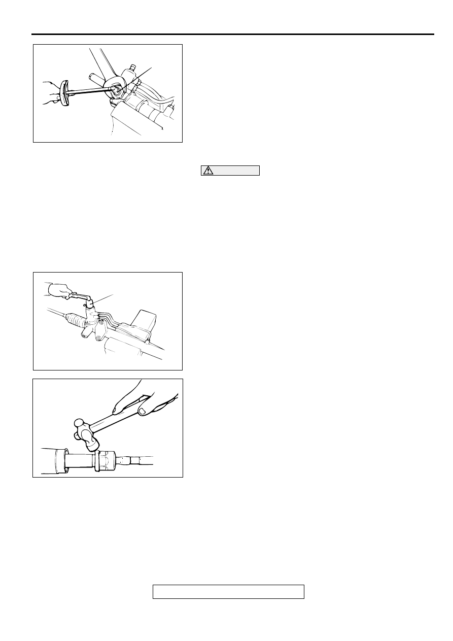
3. Use special tool MB991204 to tighten rack support cover to 

13 N

m (113 in-lb).

4. Turn the rack support cover by 10 degree counterclockwise.

5. Use special tool MB991204 to hold the rack support cover, 

and then tighten the jam nut to 59 

±

 10 N

m (44 

±

 7 ft-lb).

>>L<< TOTAL PINION TORQUE ADJUSTMENT

CAUTION

When adjusting, set at the highest value of the standard 
value range.

Be sure there is no ratcheting or catching when 
operating the rack towards the shaft.

Measure the total pinion torque through the whole 
stroke of the rack.

NOTE: If the total pinion toque cannot be adjusted to the 
standard value within the specified return angle, check the rack 
support cover components and replace any parts if necessary.
1. Using special tool MB990228 or MB991006, rotate the 

pinion shaft at the rate of one rotation in four to six seconds 
to check the total pinion torque and the change in torque.

Standard value:
Total pinion torque: 0.8 

−−−−

 1.9 mm (6.9 

−−−−

 16.5 in-lb) 

[Change in torque: 0.7 N

⋅⋅⋅⋅

m (6.1 in-lb) or less]

2. If the total pinion torque or the change in torque is outside 

the standard value, return the rack support cover within 0 
degree angle to 30 degree angle, and adjust again.

>>M<< TAB WASHER/TIE ROD INSTALLATION
After installing tie rod to rack, fold tab washer end (two 
locations) to tie rod notch.

AC001009 AB

MB991204

AC000996 AB

MB990228
OR 
MB991006

ACX01163 AB

POWER STEERING GEAR BOX ASSEMBLY

TSB Revision

POWER STEERING

37A-36

>>N<< BELLOWS BAND INSTALLATION
1. Turn the adjusting  bolt of special tool MB991561 to adjust 

the opening dimension (W) to the standard value.

NOTE: The dimension (W) is adjusted by approximately 0.7 
mm (0.03 inch) per one turn.

NOTE: Do not turn the adjusting bolt more than one turn.

Standard value (W): 1.9 mm (0.07 inch)
<When more than 1.9 mm (0.07 inch)>: Screw in the 
adjusting bolt.
<When less than 1.9 mm (0.07 inch)>: Loosen the 
adjusting bolt.

CAUTION

Hold the rack housing, and use special tool MB991561 
to crimp the bellows band securely.

Crimp the bellows band until special tool MB991561 
touches the stopper.

2. Use special tool MB991561 to crimp the bellows band.

3. Check that crimped width (A) is within the standard value.

Standard value (A): 1.4 

−−−−

 1.8 mm (0.06 

−−−−

 0.07 inch)

<When more than 1.8 mm (0.07 inch)>: Readjust the 
dimension (W) of step (1) to the value calculated by 
the following equation, and repeat step (2).
 W = 5.5 mm (0.22 inch) 

−−−−

 A [Example: if (A) is 1.9 mm 

(0.07 inch), (W) is 3.6 mm (0.14 inch).]
<When less than 1.4 mm (0.06 inch)>: Remove the 
bellows band, readjust the dimension (W) of step (1) to 
the value calculated by the following equation, and 
use a new bellows band to repeat steps (2) to (3).
W = 5.5 mm (0.22 inch) 

−−−−

 A [Example: if (A) is 1.3 mm 

(0.05 inch), (W) is 4.2 mm (0.17 inch).]

>>O<< TIE ROD END/TIE ROD END JAM NUT 
INSTALLATION
Screw in the tie rod end to achieve the right and left length as 
illustrated. Lock with the jam nut.

 INSPECTION

M1372004400040

RACK

Check the rack tooth surfaces for damage or wear.

Check the oil seal contact surfaces for uneven wear.

ACX01164 AB

W

MB991561

ADJUSTING BOLT

STOPPER

ACX01165 AB

MB991561

ACX01166 AB

A

AC001011 AB

JAM NUT

EDGE OF BELLOWS
ASSEMBLY GROOVE

2.4L ENGINE: 192 mm (7.6 in)
3.0L ENGINE: 200 mm (7.9 in)

POWER STEERING OIL PUMP ASSEMBLY

TSB Revision

POWER STEERING

37A-37

Check the rack for bends.

PINION AND VALVE ASSEMBLY

Check the pinion gear tooth surfaces for damage or wear.

Check for worn or defective seal ring.

BEARING

Check for roughness or abnormal noise during bearing 
operation.

Check the bearing for play.

Check the needle roller bearings for roller slip-off.

OTHERS

Check the cylinder inner surface of the rack housing for 
damage.

Check the boots for damage, cracking or deterioration.

Check the rack support for uneven wear or dents.

Check the rack bushing for uneven wear or damage.

TIE ROD END BALL JOINT DUST COVER 
REPLACEMENT

M1372008200071

If the dust cover is damaged accidentally during service work, 
replace the dust cover as follows:
1. Apply grease to the lip and inside of the dust cover.

2. Drive in the dust cover with special tool MB990776 until it is 

fully seated.

3. Check the dust cover for cracks or damage by pushing it 

with your finger.

PO W ER  STEER IN G  O IL PU M P A SSEM BLY

REMOVAL AND INSTALLATION

M1372005200050

AC001012AB

MB990776

Pre-removal Operation
Power Steering Fluid Draining (Refer to 

P.37A-16

.)

Post-installation Operation

Power Steering Fluid Level Check (Refer to 

P.37A-16

.)

Drive Belt Tension Check (Refer to 

P.37A-16

.)

Power Steering Fluid Line Bleeding (Refer to 

P.37A-16

.)

Oil Pump Pressure Test (Refer to 

P.37A-18

.)

POWER STEERING OIL PUMP ASSEMBLY

TSB Revision

POWER STEERING

37A-38

INSPECTION

M1372005300046

Check the drive belt for cracks.
Check the drive shaft assembly for uneven rotation.

AC001013

1

10

9

8

7

6

5

4

3

2

57 N·m
42 ft-lb

1

9

5

4

3

2

57 N·m
42 ft-lb

28 N·m
21 ft-lb

28 N·m
21 ft-lb

49 N·m
36 ft-lb

42 N·m
31 ft-lb

42 N·m
31 ft-lb

24 N·m
18 ft-lb

44 N·m
32 ft-lb

<2.4L ENGINE>

<3.0L ENGINE>

AC

49 N·m
36 ft-lb

REMOVAL STEPS

1.

DRIVE BELT

2.

PRESSURE SWITCH CONNECTOR

3.

SUCTION HOSE

4.

PRESSURE HOSE

5

.

GASKET

6.

BOLT

7.

BOLT

8.

POWER STEERING PUMP 
BRACKET

9.

OIL PUMP

10.

OIL PUMP BRACKET

REMOVAL STEPS (Continued)


Content   ..  549  550  551  552   ..