Mitsubishi Galant. Manual - part 534


  Index      Mitsubishi     Mitsubishi Galant - service repair manual 2001 year


Search            


Content   ..  532  533  534  535   ..


Mitsubishi Galant. Manual - part 534


TRACTION CONTROL SYSTEM (TCL) DIAGNOSIS

TSB Revision

TRACTION CONTROL SYSTEM (TCL)

35C-17

STEP: 2. Check the TCL indicator light bulb.
(1) Remove the combination meter (Refer to GROUP 54A, 

Combination Mete

P.54A-65

.).

(2) Check the TCL indicator light bulb.

Q: Is the TCL indicator light bulb burned out?

YES : Replace the bulb and then go to Step 9.
NO :  Go to Step 3.

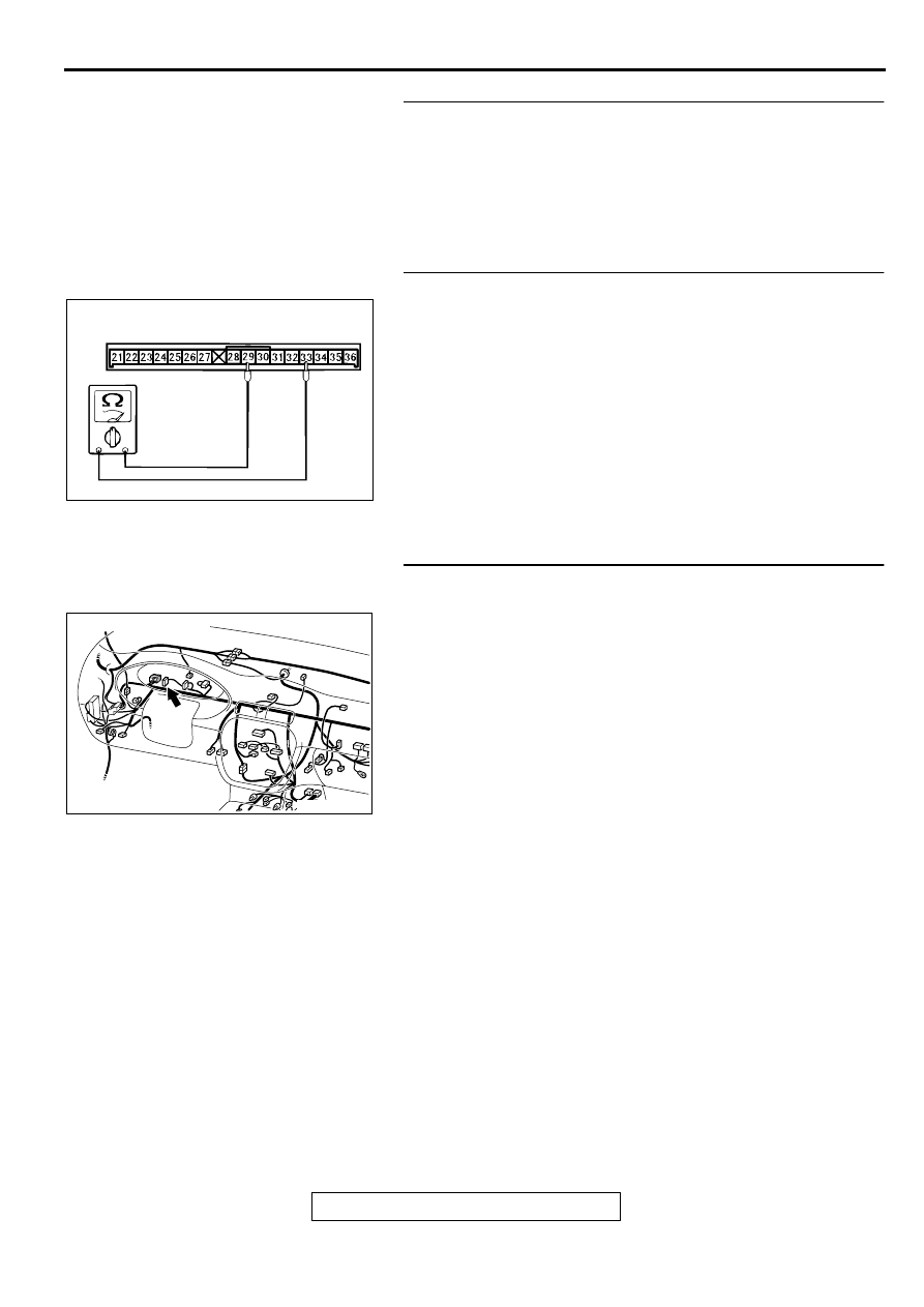
STEP: 3. Check the combination meter for the continuity.
(1) Remove the combination meter.
(2) Remove the TCL indicator light bulb. Then measure the 

resistance between the bulb terminals.

(3) Install the TCL indicator light bulb to the combination meter, 

and then measure the resistance between connector C-29 
terminals 29 and 33. The resistance reading at this time 
should be much the same as the resistance measured at 
step (2).

Q: Are the two resistance values extremely different each 

other?
YES : 
Replace the combination meter (printed circuit board).
NO (much the same) : Go to Step 4.

STEP: 4. Check the power supply circuit at the 
combination meter.
(1) Disconnect connector C-29, and check at the harness side.
(2) Turn the ignition switch to "ON" position.
(3) Measure the voltage between terminal 29 and ground. It 

should be approximately 12 volts (battery positive voltage).

Q: Is the voltage approximately 12 volts?

YES : Go to Step 5.
NO :  Go to Step 7.

AC003700AB

CONNECTOR: C-29

AC005076AB

CONNECTOR: C-29

TRACTION CONTROL SYSTEM (TCL) DIAGNOSIS

TSB Revision

TRACTION CONTROL SYSTEM (TCL)

35C-18

STEP: 5. Check connectors C-12, C-29, and A-03.
Check connectors C-12, C-29, and A-03 (Refer to GROUP 
00E, Harness Connector Inspection 

P.00E-2

.).

Q: Is any of connectors damaged?

YES : Repair it and then go to Step 9.
NO :  Go to Step 6 .

AC003695 AB

CONNECTOR: A-03

AC005077AB

CONNECTOR: C-12

AC005076AB

CONNECTOR: C-29

TRACTION CONTROL SYSTEM (TCL) DIAGNOSIS

TSB Revision

TRACTION CONTROL SYSTEM (TCL)

35C-19

STEP 6. Check the continuity between the combination 
meter and the ABS-ECU.
Check the continuity between combination meter connector C-
29 and ABS-ECU connector A-03.

Q: Is there the continuity between combination meter 

connector C-29 and ABS-ECU connector A-03?
YES : 
Go to Step 9.
NO :  Repair the harness wire and then go to Step 9.

STEP 7. Check connectors C-29, C-73, and C-78.
Check connectors C-29, C-73, and C-78 (Refer to GROUP 
00E, Harness Connector Inspection 

P.00E-2

.).

Q: Are any of the connectors damaged?

YES : Repair it and then go to Step 9.
NO :  Go to Step 8.

AC003695 AB

CONNECTOR: A-03

AC005076AB

CONNECTOR: C-29

AC005076AB

CONNECTOR: C-29

AC003082 AM

CONNECTORS: C-73, C-78

C-73

C-78

JUNCTION BLOCK
(FRONT VIEW)

TRACTION CONTROL SYSTEM (TCL) DIAGNOSIS

TSB Revision

TRACTION CONTROL SYSTEM (TCL)

35C-20

STEP 8. Check the continuity between the ignition switch 
(IG1) and the combination meter.
Q: Is there any continuity (less than 2 ohm) between the 

ignition switch (IG1) and combination meter connector 
C-29?
YES : 
Go to Step 9.
NO :  Repair the harness wire and then go to Step 9.

STEP 9. Check symptoms

Q: Does the TCL indicator light illuminate 60 seconds 

when the ignition switch is turned to the "ON" position 
with engine stopped or upon startup?
YES : 
This diagnosis is complete.
NO :  Return to Step 1.

AC005076AB

CONNECTOR: C-29


Content   ..  532  533  534  535   ..