Mitsubishi Galant. Manual - part 434


  Index      Mitsubishi     Mitsubishi Galant - service repair manual 2001 year


Search            


Content   ..  432  433  434  435   ..


Mitsubishi Galant. Manual - part 434


AUTOMATIC TRANSAXLE DIAGNOSIS

TSB Revision

AUTOMATIC TRANSAXLE

23A-203

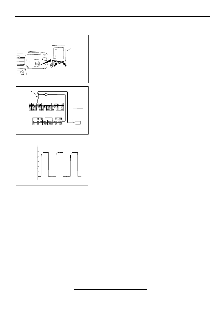
STEP 3. Using the oscilloscope, check the waveform at 
PCM connectors C-40 and C-42 by backprobing.
(1) Do not disconnect connectors C-40 and C-42.

(2) Connect an oscilloscope probe to PCM connector C-40 

terminal 57 and to PCM connector C-42 terminal 103 by 
backprobing.

(3) Start the engine and run at constant speed of 50km/h 

(31mph). (Gear range: 3rd gear)

(4) Check the waveform.

The waveform should show a pattern similar to the 
illustration. The maximum value should be 4.8 volts and 
more and the minimum value 0.8 volts and less. The 
output waveform should not contain the noise.

(5) Turn the ignition switch to "LOCK"(OFF) position.

Q: Is the waveform normal?

YES : Go to Step 8.
NO :  Go to Step 4.

AC004197

PCM

C-40

C-42

CONNECTORS: C-40, C-42

AE

AC001899

C-42 CONNECTOR HARNESS SIDE VIEW

C-40 CONNECTOR HARNESS SIDE VIEW

AE

OSCILLO-
SCOPE

PROBE

ACX02131AB

NORMAL WAVEFORM

(V)

5

0

AUTOMATIC TRANSAXLE DIAGNOSIS

TSB Revision

AUTOMATIC TRANSAXLE

23A-204

STEP 4. Check connectors B-40 at input shaft speed 
sensor and C-42 at PCM for damage.
Q: Are the connectors in good condition?

YES : Go to Step 5.
NO :  Repair or replace it. Refer to GROUP 00E, Harness 

Connector Inspection 

P.00E-2

.

STEP 5. Check harness for damage between input shaft 
speed sensor connector B-40 terminal 2 and PCM 
connector C-42 terminal 103.
Q: Is the harness wire in good condition?

YES : Go to Step 6.
NO :  Repair it.

AC001835

CONNECTOR: B-40

AF

AC004197

PCM

AF

CONNECTOR: C-42

AC001835

CONNECTOR: B-40

AF

AC004197

PCM

AF

CONNECTOR: C-42

AUTOMATIC TRANSAXLE DIAGNOSIS

TSB Revision

AUTOMATIC TRANSAXLE

23A-205

STEP 6. Replace the input shaft speed sensor.
(1) Replace the input shaft speed sensor. Refer to GROUP 

23B, Transaxle 

P.23B-10

.

(2) Carry out a test drive.
(3) Read in the A/T diagnostic trouble code.

Q: Is the A/T diagnostic trouble code "52" is output?

YES : Go to Step 7.
NO :  The inspection is complete.

STEP 7. Replace the underdrive clutch retainer.
(1) Replace the underdrive clutch retainer. Refer to GROUP 

23B, Underdrive Clutch and Input Shaft 

P.23B-51

.

(2) Carry out a test drive.
(3) Read in the diagnostic trouble code (DTC).

Q: Is the A/T diagnostic trouble code "52" is output?

YES : The A/T diagnostic trouble code may have set due to 

external radio frequency (RFI), possibly caused by 
cellular phone activity, after market components 
installed on the vehicle, etc.

NO :  The inspection is complete.

STEP 8. Replace the valve body.
(1) Replace the valve body. Refer to GROUP 23B, Transaxle 

P.23B-10

.

(2) Carry out a test drive.
(3) Read in the A/T diagnostic trouble code.

Q: Is the A/T diagnostic trouble code "52" is output?

YES : Go to Step 9.
NO :  The inspection is complete.

STEP 9. Replace the PCM.
(1) Replace the PCM.
(2) Carry out a test drive.
(3) Read in the A/T diagnostic trouble code.

Q: Is the A/T diagnostic trouble code "52" is output?

YES : Replace the torque converter. Refer to GROUP 23B, 

Transaxle 

P.23B-10

.

NO :  The inspection is complete.

AC001835

INPUT SHAFT
SPEED SENSOR

AC

AC001836AB

AC001860 AB

VALVE
BODY
ASSEMBLY

AUTOMATIC TRANSAXLE DIAGNOSIS

TSB Revision

AUTOMATIC TRANSAXLE

23A-206

DTC 53: Torque Converter Clutch is Stuck On

DTC SET CONDITIONS
If the torque converter clutch remains engaged for a 
continuous period of ten seconds when the PCM is 
attempting to disengage the torque converter clutch, 
it is judged that the torque converter clutch is stuck 
on and diagnostic trouble code number "53" is 
output.

TROUBLESHOOTING HINTS (The most likely 

causes for this code to be set:)

Malfunction of the torque converter clutch 
solenoid valve

Malfunction of the valve body

Damaged harness, connector

Malfunction of the PCM

DIAGNOSIS

Required Special Tool:
MB991502: Scan Tool (MUT-II)

STEP 1. Using scan tool MB991502, check data list item 52: 
Amount of Torque Converter Clutch Slippage.

CAUTION

To prevent damage to scan tool MB991502, always turn the 
ignition switch to "LOCK" (OFF) position before 
connecting or disconnecting scan tool MB991502.
(1) Connect scan tool MB991502 to the data link connector.
(2) Start the engine and run at constant speed of 50km/h 

(31mph). (Gear range: 3rd gear)

(3) Set scan tool MB991502 to data reading mode for item 52: 

Amount of Torque Converter Clutch Slippage.

Driving at constant speed of 50 km/h (31 mph), the 
display should be "

10 to 10 r/min."

The display should be "

300 to 

100 r/min" or "100 to 

300 r/min" when the accelerator pedal is released (50 
km/h (31 mph) and less).

(4) Turn the ignition switch to "LOCK" (OFF) position.

Q: Is the sensor operating properly?

YES : This malfunction is intermittent. Refer to GROUP 00, 

How to Use Troubleshooting/Inspection Service 
Points 

 How to Cope with Intermittent Malfunction 

P.00-8

.

NO :  Go to Step 2.

STEP 2. Using scan tool MB991502, check actuator test 
item 06: Torque Converter Clutch Solenoid Valve.
(1) Connect scan tool MB991502 to the data link connector.
(2) Turn the ignition switch to "ON" position.
(3) Set scan tool MB991502 to actuator test mode for item 06: 

Torque Converter Clutch Solenoid Valve.

An operation sound should be heard from solenoid 
valve when the torque converter clutch solenoid valve is 
operated.

(4) Turn the ignition switch to "LOCK" (OFF) position.

Q: Is the solenoid valve operating properly?

YES : Go to Step 3.
NO :  Replace the torque converter clutch solenoid valve. 

Refer to GROUP 23B, Valve Body 

P.23B-68

.

AC003081AC

MB991502

DATA LINK
CONNECTOR

AC003081AC

MB991502

DATA LINK
CONNECTOR


Content   ..  432  433  434  435   ..