Mitsubishi Galant. Manual - part 419


  Index      Mitsubishi     Mitsubishi Galant - service repair manual 2001 year


Search            


Content   ..  417  418  419  420   ..


Mitsubishi Galant. Manual - part 419


AUTOMATIC TRANSAXLE DIAGNOSIS

TSB Revision

AUTOMATIC TRANSAXLE

23A-143

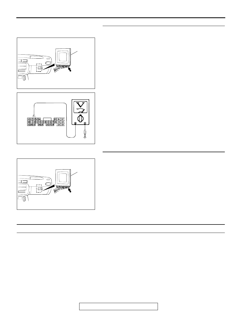
STEP 33. Check the switch output voltage at PCM 
connector C-42 by backprobing.
(1) Do not disconnect connector C-42.
(2) Turn the ignition switch to "ON" position.
(3) Move the selector lever to "L" position.

(4) Measure the voltage between terminal 110 and ground by 

backprobing.

Voltage should be battery positive voltage.

(5) Turn the ignition switch to "LOCK" (OFF) position.

Q: Is the voltage normal?

YES : Go to Step 10.
NO :  Go to Step 34.

STEP 34. Check connector C-42 at PCM for damage.
Q: Is the connector in good condition?

YES : Repair it because of the harness open circuit or short 

circuit to ground between the Park/Neutral position 
switch connector B-39 terminal 6 and PCM connector 
C-42 terminal 110.

NO :  Repair or replace it. Refer to GROUP 00E, Harness 

Connector Inspection 

P.00E-2

.

DTC 28: Park/Neutral Position Switch System (Short Circuit)

Park/Neutral Position Switch System Circuit
Refer to 

P.23A-124

.

CIRCUIT OPERATION
Refer to 

P.23A-124

.

DTC SET CONDITIONS
If the PCM detects more than one kind of park/
neutral position switch input signals for continuous 
period of thirty seconds, it is judged that there is a 
short circuit in the Park/Neutral position switch and 
diagnostic trouble code number "28" is output.

TROUBLESHOOTING HINTS (The most likely 

causes for this code to be set:)

Malfunction of the Park/Neutral position switch

Malfunction of the ignition switch

Damaged harness, connector

Malfunction of the PCM

AC004197

PCM

AF

CONNECTOR: C-42

AC001946

C-42 CONNECTOR
HARNESS SIDE VIEW

AE

AC004197

PCM

AF

CONNECTOR: C-42

AUTOMATIC TRANSAXLE DIAGNOSIS

TSB Revision

AUTOMATIC TRANSAXLE

23A-144

DIAGNOSIS

Required Special Tool:
MB991502: Scan Tool (MUT-II)

STEP 1. Check the Park/Neutral position switch.

Check for continuity between terminals for each selector 
position.

Q: Is the switch operating properly?

YES : Go to Step 2.
NO :  Replace the Park/Neutral position switch. Refer to 

GROUP 23B, Transaxle 

P.23B-10

.

STEP 2. Check connector B-39 at the Park/Neutral position 
switch for damage.
Q: Is the connector in good condition?

YES : Go to Step 3.
NO :  Repair or replace it. Refer to GROUP 00E, Harness 

Connector Inspection 

P.00E-2

.

ITEMS

TERMINAL CONNECTION 
OF TESTER

SPECIFIED
CONDITION

P

 8, 9 

 10

Less than 2 ohm.

R

 8

N

 8, 9 

 10

D

 8

3

 8

2

 8

L

 8

AC004672

DIPSTICK

PARK/NEUTRAL
POSITION (PNP)
SWITCH

AC

AC001846

P

R

N

D

3

2

L

AB

AC001844AI

CONNECTOR: B-39

DIPSTICK

AUTOMATIC TRANSAXLE DIAGNOSIS

TSB Revision

AUTOMATIC TRANSAXLE

23A-145

STEP 3. Check connector C-42 at PCM for damage.
Q: Is the connector in good condition?

YES : Go to Step 4.
NO :  Repair or replace it. Refer to GROUP 00E, Harness 

Connector Inspection 

P.00E-2

.

STEP 4. Check the switch output voltage at PCM 
connector C-42 by backprobing. ("P" position)
(1) Do not disconnect connector C-42.
(2) Turn the ignition switch to "ON" position.

(3) Measure the voltage between terminal 101 and ground by 

backprobing.

When selector lever position is "P," voltage should be 
battery positive voltage.

When selector lever position is "R," voltage should be 
0.5 volt or less.

When selector lever position is "N," voltage should be 
0.5 volt or less.

When selector lever position is "D," voltage should be 
0.5 volt or less.

When selector lever position is "3," voltage should be 
0.5 volt or less.

When selector lever position is "2," voltage should be 
0.5 volt or less.

When selector lever position is "L," voltage should be 
0.5 volt or less.

Q: Is the voltage normal?

YES : Go to Step 5.
NO :  Turn the ignition switch to "LOCK" (OFF) position. 

Repair it because of the harness damage between 
the Park/Neutral position switch connector B-39 
terminal 3 and PCM connector C-42 terminal 101.

AC004197

PCM

AF

CONNECTOR: C-42

AC004197

PCM

AF

CONNECTOR: C-42

AC001903

C-42 CONNECTOR
HARNESS SIDE VIEW

AE

AUTOMATIC TRANSAXLE DIAGNOSIS

TSB Revision

AUTOMATIC TRANSAXLE

23A-146

STEP 5. Check the switch output voltage at PCM 
connector C-42 by backprobing. ("R" position)
Measure the voltage between terminal 108 and ground by 
backprobing.

When selector lever position is "P," voltage should be 0.5 
volt or less.

When selector lever position is "R," voltage should be 
battery positive voltage.

When selector lever position is "N," voltage should be 0.5 
volt or less.

When selector lever position is "D," voltage should be 0.5 
volt or less.

When selector lever position is "3," voltage should be 0.5 
volt or less.

When selector lever position is "2," voltage should be 0.5 
volt or less.

When selector lever position is "L," voltage should be 0.5 
volt or less.

Q: Is the voltage normal?

YES : Go to Step 6.
NO :  Turn the ignition switch to "LOCK" (OFF) position. 

Repair it because of the harness damage between 
the Park/Neutral position switch connector B-39 
terminal 7 and PCM connector C-42 terminal 108.

STEP 6. Check the switch output voltage at PCM 
connector C-42 by backprobing. ("N" position)
Measure the voltage between terminal 121 and ground by 
backprobing.

When selector lever position is "P," voltage should be 0.5 
volt or less.

When selector lever position is "R," voltage should be 0.5 
volt or less.

When selector lever position is "N," voltage should be 
battery positive voltage.

When selector lever position is "D," voltage should be 0.5 
volt or less.

When selector lever position is "3," voltage should be 0.5 
volt or less.

When selector lever position is "2," voltage should be 0.5 
volt or less.

When selector lever position is "L," voltage should be 0.5 
volt or less.

Q: Is the voltage normal?

YES : Go to Step 7.
NO :  Turn the ignition switch to "LOCK" (OFF) position. 

Repair it because of the harness damage between 
the Park/Neutral position switch connector B-39 
terminal 4 and PCM connector C-42 terminal 121.

AC001904

C-42 CONNECTOR
HARNESS SIDE VIEW

AE

AC001905

C-42 CONNECTOR
HARNESS SIDE VIEW

AE


Content   ..  417  418  419  420   ..