Mitsubishi Galant. Manual - part 309


  Index      Mitsubishi     Mitsubishi Galant - service repair manual 2001 year


Search            


Content   ..  307  308  309  310   ..


Mitsubishi Galant. Manual - part 309


MULTIPORT FUEL INJECTION(MFI) DIAGNOSIS

TSB Revision

MULTIPORT FUEL INJECTION (MFI) <3.0L>

13B-461

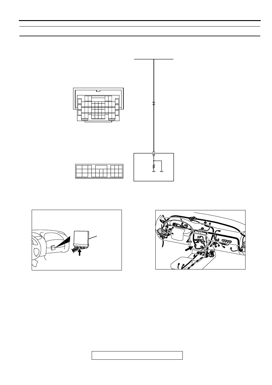
INSPECTION PROCEDURE 27: Incorrect Idle Speed When the A/C is Operating (A/C Switch 2 Signal)

CIRCUIT OPERATION

The PCM increases the engine idle speed by 
driving the IAC motor when the automatic 
compressor-ECU sends a "A/C on" signal to the 
module.

The automatic compressor-ECU detects how the 
air conditioning is applying load to the engine, 
and converts the information to a voltage signal 
(High voltage= low load, Low voltage= high load). 
This voltage signal is called "A/C switch 2 signal." 
The PCM receives this A/C switch 2 signal from 
the automatic compressor controller through 
terminal 61, and determines the idle-up speed 
according to the high or low air conditioning load.

AK000523

BL

UE-

WHITE

BL

UE-

WHITE

POWERTRAIN CONTROL
MODULE(PCM)

61

33

AUTOMATIC COMPRESSOR CONTROLLER

C-17

7 8

5

3 4

35

34

10 11 12

2122 23 24

13 14 15

25 26 27

16

28

17

18 19 20

29

30 31

32 33

36 37

38

9

1 2

6

      C-40
(MU803781)

42 43
48 49 50 51 52 53 54 55 56 57

46

45

44

58 59

60 61 62 63

64 65 66

47

41

AK000280

CONNECTOR : C-40

PCM

AV

AK000566AB

CONNECTOR:C-17

MULTIPORT FUEL INJECTION(MFI) DIAGNOSIS

TSB Revision

MULTIPORT FUEL INJECTION (MFI) <3.0L>

13B-462

TROUBLESHOOTING HINTS (The most likely 
causes for this code to be set are:) 

Malfunction of the A/C control system.

Open or shorted circuit, or improper connector 
contact.

PCM failed. 

DIAGNOSIS

STEP 1. Check connector C-40 at PCM for damage.

Q: Is the connector in good condition?

YES :  Go to Step 2.
NO :  Repair or replace it. Refer to GROUP 00E, Harness 

Connector Inspection(

P.00E-2

). Then confirm that the 

malfunction symptom is eliminated.

STEP 2. Check the output voltage at PCM harness side 
connector C-40.
(1) Disconnect the connector C-40 and measure at the harness 

side.

(2) Start the engine and run at idle.
(3) Turn the A/C switch "ON".
(4) Measure the voltage between terminal 61 and ground.

If atmospheric air temperature is 15 

°

 C (59

°

 F) or less, 

the voltage should be 1 volt or less.

If atmospheric air temperature is 18

°

 C (65.4

°

 F) or 

more, the voltage should be battery positive voltage.

(5) Turn the A/C switch "OFF".
(6) Turn the ignition switch to the "LOCK" (OFF) position.

Q: Is the voltage normal?

YES :  Replace the PCM. Then confirm that the malfunction 

symptom is eliminated.

NO :  Refer to GROUP 55, Introduction To Heater, Air 

Conditioning And Ventilation Diagnosis(

P.55-4

).

AKX01505

46 45 44

43 42

41

47

48

49

50

51

52

53

54

55

56

57

66 65 64

63 62 61 60

59

58

C-40  HARNESS
SIDE CONNECTOR

AE

MULTIPORT FUEL INJECTION(MFI) DIAGNOSIS

TSB Revision

MULTIPORT FUEL INJECTION (MFI) <3.0L>

13B-463

INSPECTION PROCEDURE 28: Fans (radlator fan, A/C condenser fan) are inoperative

AK000481

2 3

1

5

1

4

8

7

2

6

3

BLUE-ORANGE

BLUE-ORANGE

POWERTRAIN CONTROL
MODULE(PCM)

FAN CONTROLLER

5V

      A-30
(MU802322)

     C-04
MU801333

2

6

18

12

11

16

5 6

7 8

21

13
27

14
28

15
29

17
30

18
31

19
32

20
33

22
34

23
35

1

24

3

26

9

2

25

10

4

      C-39
(MU803784)

AK000280

CONNECTOR : C-39

PCM

AW

ACX02501 AE

CONNECTOR : A-30

FAN
CONTROLLER

MULTIPORT FUEL INJECTION(MFI) DIAGNOSIS

TSB Revision

MULTIPORT FUEL INJECTION (MFI) <3.0L>

13B-464

CIRCUIT OPERATION

The PCM sends a duty signal to the fan controller 
according to engine coolant temperature, vehicle 
speed, and the condition of the A/C switch. (The 
closer the average voltage at the terminal comes 
to five volts, the higher the fan speed becomes).

TROUBLESHOOTING HINTS (The most likely 
causes for this code to be set are:) 

Malfunction of the fan motor relay.

Malfunction of the fan motor.

Malfunction of the fan controller.

Improper connector contact, open or short-
circuited harness wire.

PCM failed. 

DIAGNOSIS

STEP 1. Check connector C-39 at PCM for damage.
Q: Is the connector in good condition?

YES :  Go to Step 2.
NO :  Repair or replace it. Refer to GROUP 00E, Harness 

Connector Inspection(

P.00E-2

). Then confirm that the 

malfunction symptom is eliminated.

STEP 2. Check the output voltage at PCM harness side 
connector C-39.
(1) Disconnect the connector C-39 and measure at the harness 

side.

(2) Turn the ignition switch to the "ON" position.
(3) Measure the voltage between terminal 18 and ground.

Voltage should be between 4.8 and 5.2 volts. (Fan 
rotates at high speed.)

(4) Connect a jumper cable between 18 and ground.

The fan should stop.

(5) Turn the ignition switch to the "LOCK"(OFF) position.

Q: Is the voltage and fan condition normal?

YES : Replace the PCM. Then confirm that the malfunction 

symptom is eliminated.

NO :  Go to Step 3.

AK000633 AE

CONNECTOR:C-04

AK000280

CONNECTOR : C-39

PCM

AW

AK000401

8 7

6 5

4 3

2

1
9

10

11

12

13

14

15

16

17

18

19

20

21

22

23
3534

33 32

30

29 28 27 26

25 24

C-39   HARNESS
SIDE  CONNECTOR

AC


Content   ..  307  308  309  310   ..