Mitsubishi Galant. Manual - part 290


  Index      Mitsubishi     Mitsubishi Galant - service repair manual 2001 year


Search            


Content   ..  288  289  290  291   ..


Mitsubishi Galant. Manual - part 290


MULTIPORT FUEL INJECTION(MFI) DIAGNOSIS

TSB Revision

MULTIPORT FUEL INJECTION (MFI) <3.0L>

13B-385

TECHNICAL DESCRIPTION

The PCM is checks the open circuit of battery 
backup line.

DTC SET CONDITIONS

Check Conditions

Ignition switch: ON

Judgement Criteria

The backup memory is lost.

TROUBLESHOOTING HINTS (The most likely 
causes for this code to be set are:)

Open or shorted battery backup line, or loose 
connector.

PCM failed.

DIAGNOSIS

Required Special Tools
MB991502: Scan Tool (MUT-II)

STEP 1. Check if the battery terminal is disconnected.

Q: Is the battery terminal disconnected before reading the 

DTC?
YES : 
Turn the ignition switch to the "LOCK" (OFF) position, 

and then in 10 seconds turn the ignition switch to the 
"ON" position. Then go to Step 2.

NO :  Go to Step 3.

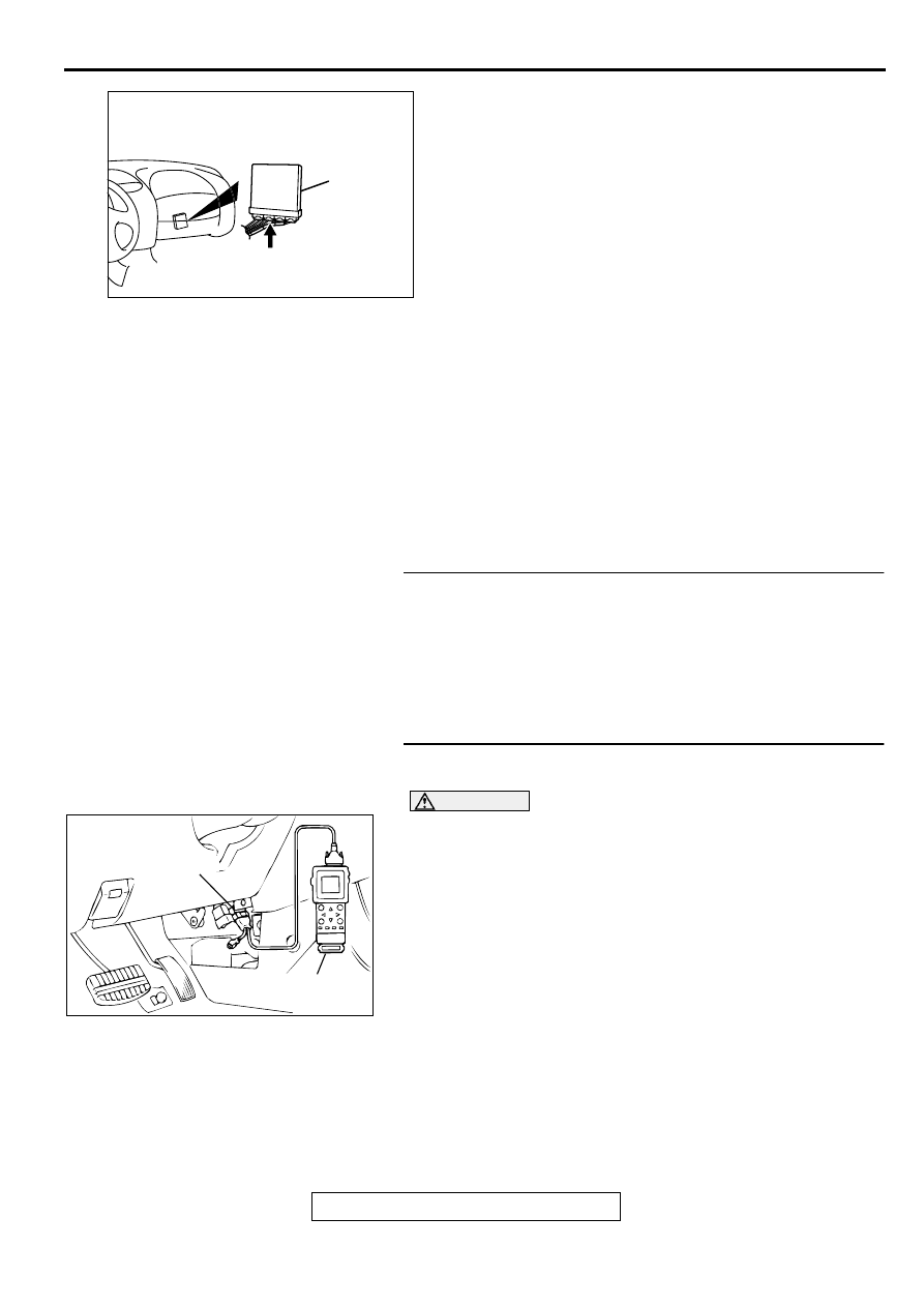
STEP 2. Using scan tool MB991502, read the diagnostic 
trouble code (DTC).

CAUTION

To prevent damage to scan tool MB991502, always turn the 
ignition switch to the "LOCK" (OFF) position before 
connecting or disconnecting scan tool MB991502.
(1) Connect scan tool MB991502 to the data link connector.
(2) Turn the ignition switch to the "ON" position.
(3) Read the DTC.
(4) Turn the ignition switch to the "LOCK" (OFF) position.

Q: Is the DTC P1603 is output?

YES : Go to Step 3.
NO :  The inspection is complete.

AK000280

CONNECTOR : C-40

PCM

AV

AC003081 AB

16 PIN

MB991502

MULTIPORT FUEL INJECTION(MFI) DIAGNOSIS

TSB Revision

MULTIPORT FUEL INJECTION (MFI) <3.0L>

13B-386

STEP 3. Check the backup power supply voltage at PCM 
connector C-40 by backprobing.
(1) Do not disconnect the connector C-40.
(2) Measure the voltage between terminal 66 and ground by 

backprobing.

Voltage should be battery positive voltage.

Q: Is the voltage normal?

YES : Go to Step 6.
NO :  Go to Step 4.

STEP 4. Check the backup power supply voltage at PCM 
harness side connector C-40.
(1) Disconnect the connector C-40 and measure at the harness 

side.

(2) Measure the voltage between terminal 66 and ground.

Voltage should be battery positive voltage.

Q: Is the voltage normal?

YES : Go to Step 5.
NO :  Check connectors C-17 and C-66 at intermediate 

connector for damage, and repair or replace as 
required. Refer to GROUP 00E, Harness Connector 
Inspection (

P.00E-2

). If intermediate connector are in 

good condition, repair harness wire between battery 
and PCM connector C-40 terminal 66 because of 
open circuit or short circuit to ground. Then go to Step 
7.

STEP 5. Check connector C-40 at PCM for damage.
Q: Is the harness connector in good condition?

YES : Check connectors C-17 and C-66 at intermediate 

connector for damage, and repair or replace as 
required. Refer to GROUP 00E, Harness Connector 
Inspection (

P.00E-2

). If intermediate connector are in 

good condition, repair harness wire between battery 
and PCM connector C-40 terminal 66 because of 
open circuit or short circuit to ground. Then go to Step 
7.

NO :  Repair or replace it. Refer to GROUP 00E, Harness 

Connector Inspection (

P.00E-2

). Then go to Step 7.

AK000731

C-40 CONNECTOR
HARNESS SIDE VIEW

46
57
66

45
56
65

44
55

43
49

54

64

42
48
59

41
47
58

53
63

52
62

51
61

50
60

AB

AKX01436

41

42

43

44

45

46
57 56 55 54 53 52

48 47

58

59

60

61

62

66 65 64

63

51 50 49

C-40   HARNESS
SIDE  CONNECTOR

AD

AK000280

CONNECTOR : C-40

PCM

AV

MULTIPORT FUEL INJECTION(MFI) DIAGNOSIS

TSB Revision

MULTIPORT FUEL INJECTION (MFI) <3.0L>

13B-387

STEP 6. Check connector C-40 at PCM for damage.
Q: Is the harness connector in good condition?

YES : Replace the PCM. Then go to Step 7.
NO :  Repair or replace it. Refer to GROUP 00E, Harness 

Connector Inspection (

P.00E-2

). Then go to Step 7.

STEP 7. Using scan tool MB991502, read the diagnostic 
trouble code (DTC).

CAUTION

To prevent damage to scan tool MB991502, always turn the 
ignition switch to the "LOCK" (OFF) position before 
connecting or disconnecting scan tool MB991502.
(1) Connect scan tool MB991502 to the data link connector.
(2) Turn the ignition switch to the "ON" position.
(3) Read the DTC.
(4) Turn the ignition switch to the "LOCK" (OFF) position.

Q: Is the DTC P1603 is output?

YES : Retry the troubleshooting.
NO :  The inspection is complete.

DTC P1610: Immobilizer Malfunction

TECHNICAL DESCRIPTION

PCM monitors the communication condition with 
the immobilizer-ECU and the message from the 
immobilizer-ECU, and when the abnormality is 
found, PCM makes the engine not to start.

DTC SET CONDITIONS

Check Conditions

Ignition switch: ON

Judgment Criteria

When the communication error between PCM 
and the immobilizer-ECU continues for 2 seconds 
or more.

When PCM receives the communication of 
prohibition for starting from the immobilizer-ECU. 

TROUBLESHOOTING HINTS (The most likely 

causes for this code to be set are:)

Malfunction of harness or connector.

Malfunction of immobilizer-ECU.

Malfunction of PCM.

DIAGNOSIS

Required Special Tools
MB991502: Scan Tool (MUT-II)

AK000280

CONNECTOR : C-40

PCM

AV

AC003081 AB

16 PIN

MB991502

MULTIPORT FUEL INJECTION(MFI) DIAGNOSIS

TSB Revision

MULTIPORT FUEL INJECTION (MFI) <3.0L>

13B-388

CAUTION

To prevent damage to scan tool MB991502, always turn the 
ignition switch to the "LOCK" (OFF) position before 
connecting or disconnecting scan tool MB991502.

STEP 1. Using scan tool MB991502, read the immobilizer 
diagnostic trouble code (DTC).
(1) Connect scan tool MB991502 to the data link connector.
(2) Turn the ignition switch to the "ON" position.
(3) Read the immobilizer system-DTC
(4) Turn the ignition switch to the "LOCK" (OFF) position.

Q: Is the immobilizer system-DTC is output?

YES : Refer to GROUP 54A, Ignition Switch and 

Immobilizer System 

 Diagnostic Trouble Code 

Chart.

P.54A-10

NO :  If DTC P1610 is output again after the MFI-DTC has 

been erased, replace the PCM. Then check that the 
DTC P1610 does not reset.

DTC P1751: A/T Control Relay Malfunction

TECHNICAL DESCRIPTION

When a malfunction of the A/T control relay is 
detected, the transaxle control CPU inside the 
powertrain control module (PCM) outputs a 
malfunction signal to the engine control CPU 
inside the PCM.

DTC SET CONDITIONS

Check Conditions, Judgment Criteria

A/T control relay failure signal is input to the 
engine control CPU from the transaxle control 
CPU.

TROUBLESHOOTING HINTS (The most likely 
causes for this code to be set are:)

A/T control relay failed.

Open or shorted A/T control relay circuit, or loose 
connector.

PCM failed.

DIAGNOSIS

Required Special Tools
MB991502: Scan Tool (MUT-II)

AC003081 AB

16 PIN

MB991502


Content   ..  288  289  290  291   ..