Mitsubishi Galant. Manual - part 279


  Index      Mitsubishi     Mitsubishi Galant - service repair manual 2001 year


Search            


Content   ..  277  278  279  280   ..


Mitsubishi Galant. Manual - part 279


MULTIPORT FUEL INJECTION(MFI) DIAGNOSIS

TSB Revision

MULTIPORT FUEL INJECTION (MFI) <3.0L>

13B-341

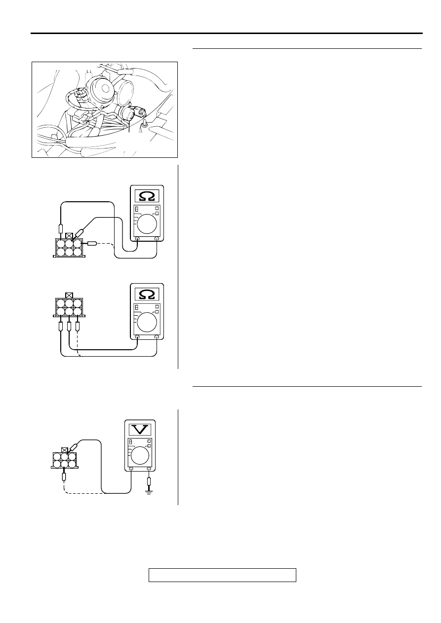
STEP 4. Check the idle air control motor coil resistance.
(1) Disconnect the idle air control motor connector B-06.
(2) Measure the resistance between idle air control motor 

connector terminal 2 and either terminal 1 or terminal 3.

Standard value: 28 

−−−−

 33 ohm [at 20

°°°°    

C (68

°°°°

 F)]

(3) Measure the resistance between idle air control motor 

connector terminal 5 and either terminal 4 or terminal 6.

Standard value: 28 

−−−−

 33 ohm [at 20

°°°°    

C (68

°°°°

 F)]

Q: Is the resistance normal?

YES : Go to Step 5.
NO :  Replace the idle air control motor. Then go to Step 14. 

STEP 5. Check the power supply voltage at idle air control 
motor harness side connector B-06.
(1) Disconnect the connector B-06 and measure at the harness 

side.

(2) Turn the ignition switch to the "ON" position.
(3) Measure the voltage between terminal 2, 5 and ground.

Voltage should be battery positive voltage.

(4) Turn the ignition switch to the "LOCK"(OFF) position.

Q: Is the voltage normal?

YES : Go to Step 7.
NO :  Go to Step 6.

ACX02523AG

IDLE AIR
CONTROL
MOTOR

CONNECTOR:B-06

AKX01561

1 2 3
4 5 6

1 2 3
4 5 6

AB

AKX01428

B-06 HARNESS SIDE
CONNECTOR

1

2

3

4

5

6

AD

MULTIPORT FUEL INJECTION(MFI) DIAGNOSIS

TSB Revision

MULTIPORT FUEL INJECTION (MFI) <3.0L>

13B-342

STEP 6. Check connector A-21X at MFI relay for damage.
Q: Is the connector in good condition?

YES : Repair harness wire between MFI relay connector A-

21X terminal 1 and idle air control motor connector B-
06 terminal 2, 5 because of open circuit or short circuit 
to ground. Then go to Step 14. 

NO :  Repair or replace it. Refer to GROUP 00E, Harness 

Connector Inspection(

P.00E-2

). Then go to Step 14.

STEP 7. Check the power supply voltage at PCM connector 
C-39 by backprobing
(1) Do not disconnect the connector C-39.
(2) Measure the voltage between terminal 14, 15, 28, 29 and 

ground by backprobing.

The voltage is 1V or lower for approximately 3 seconds, 
then changes to the battery positive voltage when the 
Ignition switch is turned from the "LOCK"(OFF) position 
to the "ON" position.

(3) Turn the ignition switch to the "LOCK"(OFF) position.

Q: Is the voltage normal?

YES : Go to Step 10.
NO :  Go to Step 8.

STEP 8. connector C-39 at PCM for damage.
Q: Is the connector in good condition?

YES : Go to Step 9.
NO :  Repair or replace it. Refer to GROUP 00E, Harness 

Connector Inspection(

P.00E-2

). Then go to Step 14.

AK000555AB

CONNECTOR : A-21X

MFI RELAY

AK000307

C-39 CONNECTOR
HARNESS SIDE VIEW

1
9

24

2

10 11
25

3

12
26

4

13
27

5

19
32

6

20 21
33

7

22
34

8

23
35

14
28

1516
29

17

30

18

31

AC

AK000280

CONNECTOR : C-39

PCM

AW

MULTIPORT FUEL INJECTION(MFI) DIAGNOSIS

TSB Revision

MULTIPORT FUEL INJECTION (MFI) <3.0L>

13B-343

STEP 9. Check for open circuit and short circuit to ground 
between idle air control motor connector B-06 and PCM 
connector C-39.

a. Idle air control motor connector B-06 terminal 1 and PCM 

connector C-39 terminal 14.

b. Idle air control motor connector B-06 terminal 3 and PCM 

connector C-39 terminal 28.

c. Idle air control motor connector B-06 terminal 4 and PCM 

connector C-39 terminal 15.

d. Idle air control motor connector B-06 terminal 6 and PCM 

connector C-39 terminal 29.

Q: Is the harness wire in good condition?

YES : Replace the PCM. Then go to Step 14.
NO :  Repair it. Then go to Step 14.

STEP 10. Check connector C-39 at PCM for damage.
Q: Is the connector in good condition?

YES : Go to Step 11.
NO :  Repair or replace it. Refer to GROUP 00E, Harness 

Connector Inspection(

P.00E-2

). Then go to Step 14.

ACX02523AG

IDLE AIR
CONTROL
MOTOR

CONNECTOR:B-06

AK000280

CONNECTOR : C-39

PCM

AW

AK000280

CONNECTOR : C-39

PCM

AW

MULTIPORT FUEL INJECTION(MFI) DIAGNOSIS

TSB Revision

MULTIPORT FUEL INJECTION (MFI) <3.0L>

13B-344

STEP 11. Check the idle air control motor operation using 
special tool MB991709.
(1) Remove the idle air control motor.
(2) Connect special tool MB991709 to the idle air control motor. 

(All terminals should be connected.)

(3) Use the jumper wires to connect terminal 2 of the idle air 

control motor connector to the battery (+) terminal.

(4) Check the ensure that the motor operates when the 

terminals 1 and 3 of the idle air control motor connector are 
respectively connected to the battery (-) terminal using a 
jumper wire.

Vibration should be present at each application of 
voltage to test clip combination.

(5) Then. Use jumper wires to connect the terminal 5 of the idle 

air control motor connector to the battery (+) terminal.

(6) Check the ensure that the motor operates when the 

terminals 4 and 6 of the idle air control motor connector are 
respectively connected to the battery (-) terminal using a 
jumper wire.

Vibration should be present at each application of 
voltage to test clip combination.

(7) Install the idle air control motor. Refer to, Throttle Body 


Disassembly and Assembly(

P.13B-530

).

Q: Is the idle air control motor operating properly?

YES : Go to Step 12.
NO :  Replace the idle air control motor. Then go to Step 14. 

ACX02523AG

IDLE AIR
CONTROL
MOTOR

CONNECTOR:B-06

AKX01626

AKX01627AB

TERMINAL 2

IAC MOTOR

TERMINAL 5

MB991709


Content   ..  277  278  279  280   ..