Mitsubishi Galant. Manual - part 272


  Index      Mitsubishi     Mitsubishi Galant - service repair manual 2001 year


Search            


Content   ..  270  271  272  273   ..


Mitsubishi Galant. Manual - part 272


MULTIPORT FUEL INJECTION(MFI) DIAGNOSIS

TSB Revision

MULTIPORT FUEL INJECTION (MFI) <3.0L>

13B-313

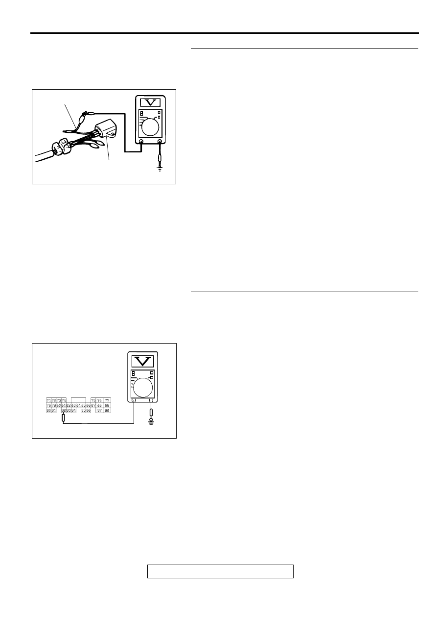
STEP 9. Check the output voltage at fuel tank differential 
pressure sensor connector D-11. 
(1) Disconnect fuel tank differential pressure sensor connector 

D-11.

(2) Use special tool (MB991658) to connect terminals 2 and 3 

of the disconnected sensor connector and those of the 
harness side connector, respectively.

(3) Turn the ignition switch to the "ON" position.
(4) Remove the fuel cap.
(5) Measure the voltage between terminal 1 and ground by 

backprobing.

Voltage should be between 2.0 and 3.0 volts.

(6) Turn the ignition switch to the "LOCK" (OFF) position.

Q: Is the multi-meter reading within the specified value?

YES : Check connectors D-15, C-71, C-17, C-41 and repair 

or replace as required. Refer to GROUP 00E, 
Harness Connector Inspection

P.00E-2

. If connectors 

D-15, C-71, C-17, C-41 are in good condition, check 
the harness between fuel tank differential pressure 
sensor connector D-11 and PCM connector C-41 for 
short circuit to ground, then repair if necessary. Then 
go to Step 26.

NO :  Replace the fuel tank differential pressure sensor. 

Then go to Step 26.

STEP 10. Check the output circuit voltage at PCM 
connector C-41. 
(1) Do not disconnect the PCM connector C-41.
(2) Turn the ignition switch to the "ON" position.
(3) Remove the fuel cap.
(4) Measure the voltage between terminal 92 and ground by 

backprobing.

Voltage should be between 2.0 and 3.0 volts.

(5) Turn the ignition switch to the "LOCK" (OFF) position.

Q: Is the multi-meter reading within the specified value?

YES : Go to Step 18.
NO :  Check connectors D-15, C-71, C-17, C-41 and repair 

or replace as required. Refer to GROUP00E, Harness 
Connector Inspection

P.00E-2

. If connectors D-15, C-

71, C-17, C-41 are in good condition, check the 
harness between intermediate connector D-15 and 
PCM connector C-41 for open circuit or damage. 
Then repair if necessary. Then go to Step 26 .

ACX01760AB

MB991658

FUEL TANK DIFFERENTIAL

PRESSURE SENSOR

AC004962 AB

C-41

HARNESS SIDE 
CONNECTOR

MULTIPORT FUEL INJECTION(MFI) DIAGNOSIS

TSB Revision

MULTIPORT FUEL INJECTION (MFI) <3.0L>

13B-314

STEP 11. Check the 5-volt supply circuit voltage at PCM 
connector C-40.
(1) Do not disconnect PCM connector C-40.
(2) Turn the ignition switch to the "ON" position.
(3) Measure the voltage between terminal 46 and ground by 

backprobing.

Voltage should be between 4.8 and 5.2 volts.

(4) Turn the ignition switch to the "LOCK" (OFF) position.

Q: Is the multi-meter reading within the specified value?

YES : Check connectors D-15, C-71, C-17, C-40 and repair 

or replace as required. Refer to GROUP 00E, 
Harness Connector Inspection

P.00E-2

. If connectors 

D-15, C-71, C-17, C-40 are in good condition, check 
the harness between intermediate connector D-15 
and PCM connector C-40 for open circuit or damage. 
Then repair if necessary. Then go to Step 26   .

NO :  Go to Step 12.

STEP 12. Check PCM connector C-40 for damage.
(1) Disconnect PCM connector C-40.

Q: Is there any failure at PCM connector C-40?

YES : Repair or replace it. Refer to GROUP 00E, Harness 

Connector Inspection

P.00E-2

. Then go to Step 26.

NO :  Go to Step 13.

STEP 13. Check the sensor power supply line for short 
circuit to ground at PCM connector C-40.
(1) Disconnect PCM connector C-40 and measure at the 

harness side.

(2) Check for the continuity between terminal 46 and ground.

There should be 2 ohms or more.

Q: Does the multi-meter reading exceed the specified 

value?
YES : 
Go to Step 26.
NO :  Go to Step 14.

AC004963AB

C-40

HARNESS SIDE 
CONNECTOR

AC005043

CONNECTOR : C-40

PCM

AC

AC004964 AB

C-40

HARNESS SIDE 
CONNECTOR

MULTIPORT FUEL INJECTION(MFI) DIAGNOSIS

TSB Revision

MULTIPORT FUEL INJECTION (MFI) <3.0L>

13B-315

STEP 14. Check the sensor power supply lines.
(1) Check all the sensor power supply lines for damage, which 

flow through the harness PCM connector (terminal 46.)

Q: Is there any failure in the sensor power supply lines?

When a failure is found : Repair if necessary. (Refer to 

GROUP 90, Circuit Diagrams 

 MFI System <3.0L 

ENGINE>

P.90-40

. Then go to Step 26.)

STEP 15. Check the ground circuit voltage at PCM 
connector C-40.
(1) Do not disconnect PCM connector C-40.
(2) Turn the ignition switch to the "ON" position.
(3) Measure the voltage between terminal 57 and ground by 

backprobing.

Voltage should be 0.5 volts or less.

(4) Turn the ignition switch to the "LOCK" (OFF) position.

Q: Is the multi-meter reading below the specified value?

YES : Check connectors D-15, C-71, C-17, C-40 and repair 

or replace as required. Refer to GROUP 00E, 
Harness Connector Inspection

P.00E-2

. If connectors 

D-15, C-71, C-17, C-40 are in good condition, check 
the harness between intermediate connector D-15 
and PCM connector C-40 for open circuit or damage. 
Then repair if necessary. Then go to Step 26   .

NO :  Go to Step 16.

STEP 16. Check PCM connector C-40 for damage.
(1) Disconnect PCM connector C-40.

Q: Is there any failure at PCM connector C-40?

YES : Repair or replace it. Refer to GROUP 00E, Harness 

Connector Inspection

P.00E-2

. Then go to Step 26.

NO :  Go to Step 26.

AC004965 AB

C-40

HARNESS SIDE 
CONNECTOR

AC005043

CONNECTOR : C-40

PCM

AC

MULTIPORT FUEL INJECTION(MFI) DIAGNOSIS

TSB Revision

MULTIPORT FUEL INJECTION (MFI) <3.0L>

13B-316

STEP 17. Check the harness between fuel tank differential 
pressure sensor connector D-11 and intermediate 
connector D-15 for open circuit or damage.
(1) Disconnect fuel tank differential pressure sensor connector 

D-11 and intermediate connector D-15.

Q: Is there any failure between fuel tank differential 

pressure sensor connector D-11 and intermediate 
connector D-15?
YES : 
Repair it. Then go to Step 26.
NO :  Check connectors D-11, D-15 and repair or replace as 

required. Refer to GROUP 00E, Harness Connector 
Inspection

P.00E-2

. Then go to Step 26.

STEP 18. Check PCM connector C-41 for damage.
(1) Disconnect PCM connector C-41.

Q: Is there any failure at PCM connector C-41?

YES : Repair or replace it. Refer to GROUP 00E, Harness 

Connector Inspection

P.00E-2

. Then go to Step 26.

NO :  Go to Step 19.

AC002041AC

CONNECTOR: D-11

FUEL TANK DIFFERENTIAL 
PRESSURE SENSOR

AC002549AC

CONNECTOR: D-15

INTERMEDIATE 
CONNECTOR

AC005043

CONNECTOR : C-41

PCM

AD


Content   ..  270  271  272  273   ..