Mitsubishi Galant. Manual - part 222


  Index      Mitsubishi     Mitsubishi Galant - service repair manual 2001 year


Search            


Content   ..  220  221  222  223   ..


Mitsubishi Galant. Manual - part 222


MULTIPORT FUEL INJECTION(MFI) DIAGNOSIS

TSB Revision

MULTIPORT FUEL INJECTION (MFI) <3.0L>

13B-113

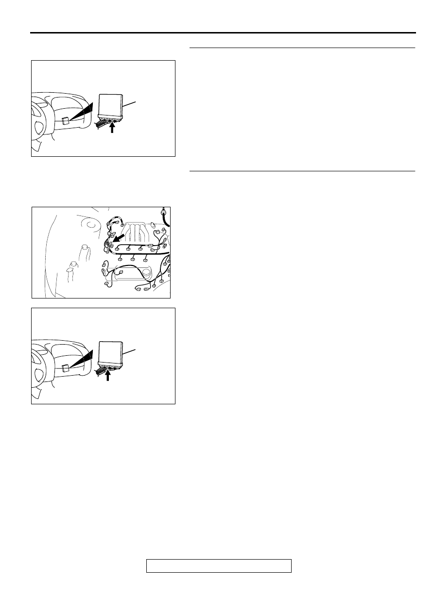
STEP 11. Check connector C-40 at PCM for damage.
Q: Is the connector in good condition?

YES : Go to Step 12.
NO :  Repair or replace it. Refer to GROUP 00E, Harness 

Connector Inspection(

P.00E-2

). Then go to Step 15.

STEP 12. Check for harness damage between right bank 
heated oxygen sensor (front) connector B-33 terminal 2 
and PCM connector C-40 terminal 57.
Q: Is the harness wire in good condition?

YES : Go to Step 13.
NO :  Repair it. Then go to Step 15.

AK000280

CONNECTOR : C-41

PCM

AY

AK000617

CONNECTOR:B-33

AB

AK000280

CONNECTOR : C-40

PCM

AV

MULTIPORT FUEL INJECTION(MFI) DIAGNOSIS

TSB Revision

MULTIPORT FUEL INJECTION (MFI) <3.0L>

13B-114

STEP 13. Check for short circuit to ground and harness 
damage between right bank heated oxygen sensor (front) 
connector B-33 terminal 4 and PCM connector C-41 
terminal 72.
Q: Is the harness wire in good condition?

YES : Go to Step 14.
NO :  Repair it. Then go to Step 15.

STEP 14. Check the right bank heated oxygen sensor 
(front).
(1) Disconnect the right bank heated oxygen sensor (front) 

connector B-33 and connect test harness special tool, 
MD998464, to the connector on the right bank heated 
oxygen sensor (front) side.

(2) Warm up the engine until engine coolant 80

°

 C (176

°

 F) or 

higher.

CAUTION

Be very careful when connecting the jumper wires; 
incorrect connection can damage the right bank heated 
oxygen sensor (front).
(3) Use the jumper wires to connect terminal 1 (red clip) to the 

positive battery terminal and terminal 3 (blue clip) to the 
negative battery terminal.

(4) Connect a digital volt meter between terminal 2 (black clip) 

and terminal 4 (white clip).

(5) While repeatedly revving the engine, measure the right 

bank heated oxygen sensor (front) output voltage.

Standard value: 0.6 

−−−−

 1.0 V

Q: Is the voltage at the standard value?

YES : Replace the PCM. Then go to Step 15.
NO :  Replace the right bank heated oxygen sensor (front). 

Then go to Step 15.

AK000617

CONNECTOR:B-33

AB

AK000280

CONNECTOR : C-41

PCM

AY

ACX02481AG

CONNECTOR:B-33

RIGHT BANNK
HEATED OXYGEN
SENSOR(FRONT)

AKX01625AC

BLUE

RED

BLACK

JUMPER
WIRES

WHITE

MD998464

MULTIPORT FUEL INJECTION(MFI) DIAGNOSIS

TSB Revision

MULTIPORT FUEL INJECTION (MFI) <3.0L>

13B-115

STEP 15. Test the OBD-II drive cycle.
(1) Carry out a test drive with the drive cycle pattern. Refer to, 

Procedure 4 

 Heated oxygen Sensor Monitor and 

Procedure 6 

 Other Monitor (

P.13B-4

).

(2) Check the diagnostic trouble code (DTC).

Q: Is the DTC P0130 is output?

YES : Retry the troubleshooting.
NO :  The inspection is complete.

MULTIPORT FUEL INJECTION(MFI) DIAGNOSIS

TSB Revision

MULTIPORT FUEL INJECTION (MFI) <3.0L>

13B-116

DTC P0133: O

2

 Sensor Circuit Slow Response (bank 1 sensor 1)

AK000501

4

1 2

3

BLA

CK

BLA

CK

BLUE

     B-33
MU802605

POWERTRAIN CONTROL
MODULE(PCM)

RIGHT BANK HEATED OXYGEN
SENSOR(FRONT)

FROM MFI RELAY

TO ECM
OR PCM

1

2

3

4

57

72

98

78

71

88 89

76 77

72
79
91

73
80

74

75

81
92

82 83
93

84 85

94

86 87

95 96

90

97

      C-41
(MU803782)

      C-40
(MU803781)

42 43
48 49 50 51 52 53 54 55 56 57

46

45

44

58 59

60 61 62 63

64 65 66

47

41


Content   ..  220  221  222  223   ..