Mitsubishi Galant. Manual - part 215


  Index      Mitsubishi     Mitsubishi Galant - service repair manual 2001 year


Search            


Content   ..  213  214  215  216   ..


Mitsubishi Galant. Manual - part 215


MULTIPORT FUEL INJECTION(MFI) DIAGNOSIS

TSB Revision

MULTIPORT FUEL INJECTION (MFI) <3.0L>

13B-85

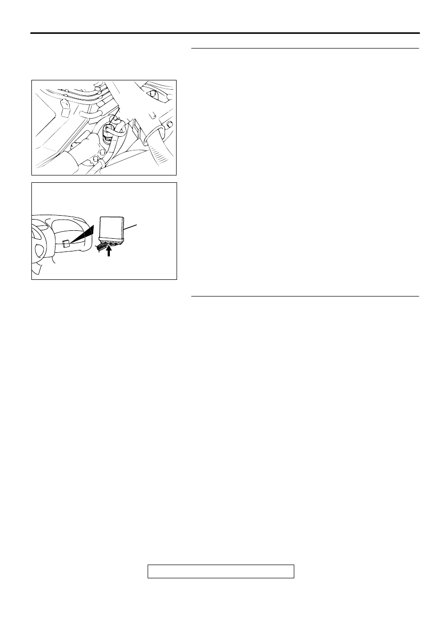
STEP 13. Check for harness damage between engine 
coolant temperature sensor connector B-13 terminal 1 and 
PCM connector C-40 terminal 44.
Q: Is the harness wire in good condition?

YES : Replace the PCM. Then go to Step 14.
NO :  Repair it. Then go to Step 14.

STEP 14. Test the OBD-II drive cycle.
(1) Carry out a test drive with the drive cycle pattern. Refer to 

P.13B-4

, Procedure 6 

 Other Monitor.

(2) Check the diagnostic trouble coed (DTC).

Q: Is the DTC P0117 is output?

YES : Retry the troubleshooting.
NO :  The inspection is complete.

ACX02490

CONNECTOR:B-13

ENGINE
COOLANT
TEMPERATURE
SENSOR

AG

AK000280

CONNECTOR : C-40

PCM

AV

MULTIPORT FUEL INJECTION(MFI) DIAGNOSIS

TSB Revision

MULTIPORT FUEL INJECTION (MFI) <3.0L>

13B-86

DTC P0121: Throttle Position Circuit Range/Performance Problem

AK000500

2 3 4

1

GREEN-YELLO

W

BR

O

WN-

WHITE

BR

O

WN-

WHITE

BLA

CK

98

78

71

88 89

76 77

72
79
91

73
80

74

75

81
92

82 83
93

84 85

94

86 87

95 96

90

97

57

78

46

5V

AUTO-CRUISE
CONTROL SYSTEM

      B-05
(MU802724)

THROTTLE POSITION
SENSOR

4

3

1

POWERTRAIN CONTROL
MODULE(PCM)

      C-41
(MU803782)

      C-40
(MU803781)

42 43
48 49 50 51 52 53 54 55 56 57

46

45

44

58 59

60 61 62 63

64 65 66

47

41

MULTIPORT FUEL INJECTION(MFI) DIAGNOSIS

TSB Revision

MULTIPORT FUEL INJECTION (MFI) <3.0L>

13B-87

CIRCUIT OPERATION

A 5-volt power supply is applied on the TPS 
power terminal (terminal 4) from the PCM 
(terminal 46).
The ground terminal (terminal 1) is grounded with 
PCM (terminal 57).

When the throttle valve shaft is turned from the 
idle position to the fully opened position, the 
resistor between the TPS output terminal 
(terminal 3) and ground terminal will increase 
according to the rotation. 

TECHNICAL DESCRIPTION

The TPS outputs voltage which corresponds to 
the throttle valve opening angle.

The PCM checks whether the voltage is within a 
specified range. In addition, it checks that the 
voltage output does not become too high while 
the engine is at idle.

DTC SET CONDITIONS

Check Conditions

Two seconds or more have passed since the 
starting sequence was completed.

Judgement Criteria

The sensor output voltage remains 2 volts or 
more for two seconds when engine speed is 
1,000 r/min or less, and volumetric efficiency is 
60% or less.

or

TPS output voltage has continued to be 0.2 volt 
or lower for 2 seconds.

TROUBLESHOOTING HINTS (The most likely 
causes for this code to be set are:)

TPS failed or maladjusted.

Open or shorted TPS circuit, or loose connector.

PCM failed.

DIAGNOSIS

Required Special Tools
MB991502: Scan Tool (MUT-II)

ACX02484 AH

THROTTLE
POSITION
SENSOR

CONNECTOR:B-05

AK000280

CONNECTORS : C-40, C-41

C-41

C-40

PCM

AX

MULTIPORT FUEL INJECTION(MFI) DIAGNOSIS

TSB Revision

MULTIPORT FUEL INJECTION (MFI) <3.0L>

13B-88

STEP 1. Using scan tool MB991502, check data list item 14: 
Throttle Position Sensor.

CAUTION

To prevent damage to scan tool MB991502, always turn the 
ignition switch to the " LOCK " (OFF) position before 
connecting or disconnecting scan tool MB991502.
(1) Connect scan tool MB991502 to the data link connector.
(2) Turn the ignition switch to the " ON " position.
(3) Set scan tool MB991502 to the data reading mode for item 

14, Throttle Position Sensor.

With the throttle valve in the idle position, voltage should 
be between 0.535 and 0.735 volts.

With the throttle valve in the full-open position, voltage 
should be between 4.5 and 5.5 volts.

(4) Turn the ignition switch to the " LOCK " (OFF) position.

Q: Is the sensor operating properly?

YES : It can be assumed that this malfunction is intermittent. 

Refer to GROUP 00, How to Use Troubleshooting/
Inspection Service Points(

P.00-8

).

NO :  Go to Step 2.

STEP 2. Check connector B-05 at throttle position sensor 
for damage.
Q: Is the connector in good condition?

YES : Go to Step 3.
NO :  Repair or replace it. Refer to GROUP 00E, Harness 

Connector Inspection(

P.00E-2

). Then go to Step 14.

STEP 3. Check the sensor supply voltage at throttle 
position sensor harness side connector B-05.
(1) Disconnect the connector B-05 and measure at the harness 

side.

(2) Turn the ignition switch to the " ON " position.
(3) Measure the voltage between terminal 4 and ground.

Voltage should be between 4.8 and 5.2 volts.

(4) Turn the ignition switch to the " LOCK " (OFF) position.

Q: Is the voltage normal?

YES : Go to Step 6.
NO :  Go to Step 4.

AC003081 AB

16 PIN

MB991502

ACX02484 AH

THROTTLE
POSITION
SENSOR

CONNECTOR:B-05

AK000236

B-05 HARNESS 
SIDE CONNECTOR

1

2

3

4

AE


Content   ..  213  214  215  216   ..