Mitsubishi Galant. Manual - part 207


  Index      Mitsubishi     Mitsubishi Galant - service repair manual 2001 year


Search            


Content   ..  205  206  207  208   ..


Mitsubishi Galant. Manual - part 207


MULTIPORT FUEL INJECTION(MFI) DIAGNOSIS

TSB Revision

MULTIPORT FUEL INJECTION (MFI) <3.0L>

13B-53

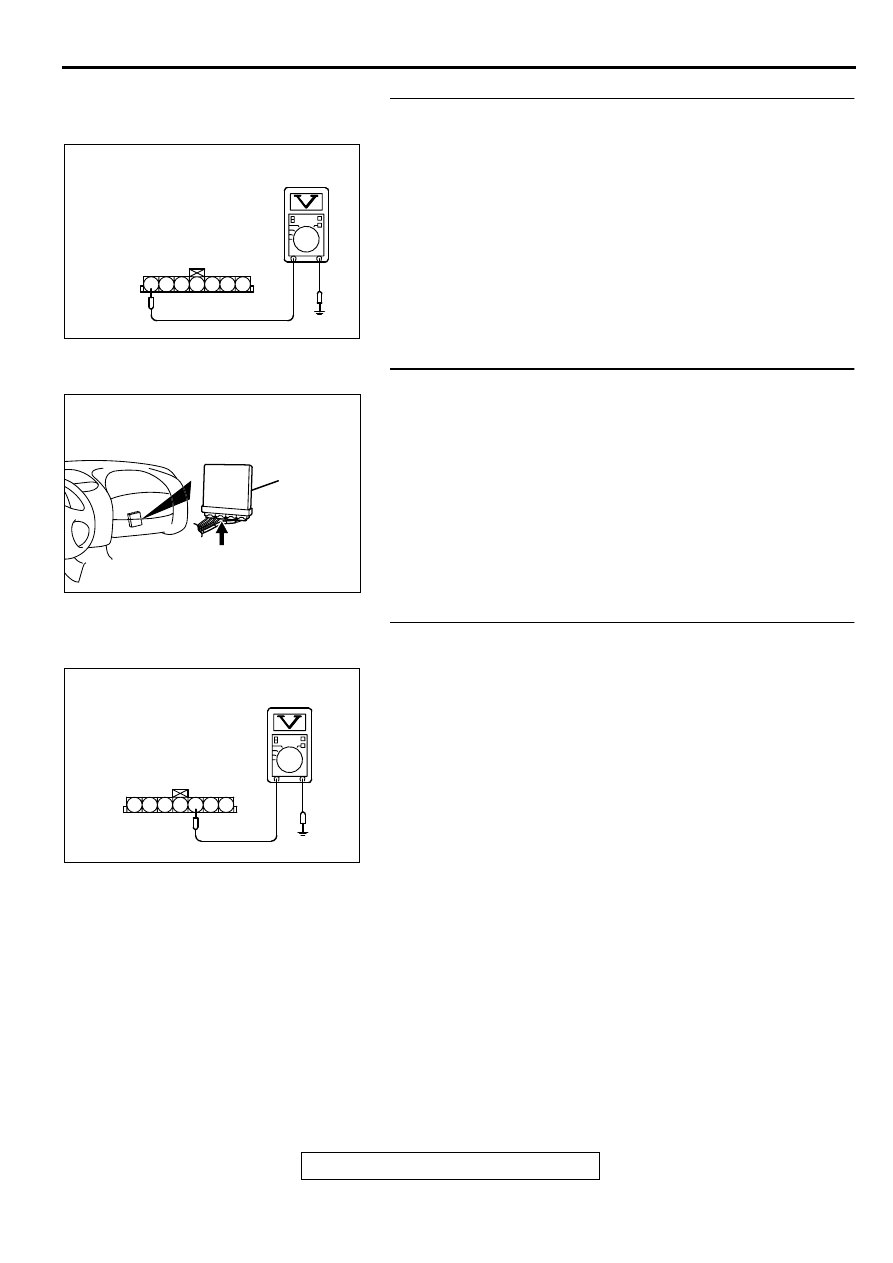
STEP 5. Check the sensor supply voltage at barometric 
pressure sensor connector B-14 by backprobing
(1) Do not disconnect the connector B-14.
(2) Turn the ignition switch to the "ON" position.
(3) Measure the voltage between terminal 1 and ground by 

backprobing.

Voltage should be between 4.8 and 5.2 volts.

(4) Turn the ignition switch to the "LOCK"(OFF) position.

Q: Is the voltage normal?

YES : Go to Step 7.
NO :  Go to Step 6.

STEP 6. Check connector C-40 at PCM for damage.
Q: Is the connector in good condition?

YES : Replace the PCM. Then go to Step 12.
NO :  Repair or replace it. Refer to GROUP 00E, Harness 

Connector Inspection(

P.00E-2

). Then go to Step 12.

STEP 7. Check the ground voltage at barometric pressure 
sensor connector B-14 by backprobing.
(1) Do not disconnect the connector B-14.
(2) Turn the ignition switch to the "ON" position.
(3) Measure the voltage between terminal 5 and ground by 

backprobing.

Voltage should be 0.5 volt or less.

(4) Turn the ignition switch to the "LOCK"(OFF) position.

Q: Is the voltage normal?

YES : Go to Step 10.
NO :  Go to Step 8.

AKX01521AC

B-14 CONNECTOR
HARNESS
SIDE VIEW

1 2 3 4 5 6 7

AK000280

CONNECTOR : C-40

PCM

AV

AKX01517

B-14 CONNECTOR
HARNESS
SIDE VIEW

1 2 3 4 5 6 7

AC

MULTIPORT FUEL INJECTION(MFI) DIAGNOSIS

TSB Revision

MULTIPORT FUEL INJECTION (MFI) <3.0L>

13B-54

STEP 8. Check connector B-14 at the barometric pressure 
sensor and connector C-40 at PCM for damage.
Q: Is the connector in good condition?

YES : Go to Step 9.
NO :  Repair or replace it. Refer to GROUP 00E, Harness 

Connector Inspection(

P.00E-2

). Then go to Step 12.

STEP 9. Check for open circuit between barometric 
pressure sensor connector B-14 terminal 5 and PCM 
connector C-40 terminal 57.
Q: Is the harness wire in good condition?

YES : Replace the PCM. Then go to Step 12.
NO :  Repair it. Then go to Step 12.

ACX02480

CONNECTOR : B-14

AF

BAROMETRIC
PRESSURE
SENSOR

AK000280

CONNECTOR : C-40

PCM

AV

ACX02480

CONNECTOR : B-14

AF

BAROMETRIC
PRESSURE
SENSOR

AK000280

CONNECTOR : C-40

PCM

AV

MULTIPORT FUEL INJECTION(MFI) DIAGNOSIS

TSB Revision

MULTIPORT FUEL INJECTION (MFI) <3.0L>

13B-55

STEP 10. Check connector B-14 at barometric pressure 
sensor for damage.
Q: Is the connector in good condition?

YES : Go to Step 11.
NO :  Repair or replace it. Refer to GROUP 00E, Harness 

Connector Inspection(

P.00E-2

). Then go to Step 12.

STEP 11. Check connector C-40 at PCM for damage.
Q: Is the connector in good condition?

YES : Replace the volume air flow sensor. Then go to Step 

12. 

NO :  Repair or replace it. Refer to GROUP 00E, Harness 

Connector Inspection(

P.00E-2

). Then go to Step 12.

STEP 12. Test the OBD-II drive cycle.
(1) Carry out a test drive with the drive cycle pattern. Refer to 

P.13B-4

, Procedure 6 

 Other Monitor.

(2) Check the diagnostic trouble code (DTC).

Q: Is the DTC P0108 is output?

YES : Retry the troubleshooting.
NO :  The inspection is complete.

ACX02480

CONNECTOR : B-14

AF

BAROMETRIC
PRESSURE
SENSOR

AK000280

CONNECTOR : C-40

PCM

AV

MULTIPORT FUEL INJECTION(MFI) DIAGNOSIS

TSB Revision

MULTIPORT FUEL INJECTION (MFI) <3.0L>

13B-56

DTC P0111: Intake air temperature Circuit Range/Performance Problem

CIRCUIT OPERATION

Approximately 5 volts are applied to the intake air 
temperature sensor output terminal (terminal 6) 
from the PCM (terminal 64) via the resistor in the 
PCM. The ground terminal (terminal 5) is 
grounded with PCM (terminal 57).

The intake air temperature sensor is a negative 
temperature coefficient type of resistor. When the 
intake air temperature rises, the resistance 
decreases.

The intake air temperature sensor output voltage 
increases when the resistance increases and 
decreases when the resistance decreases.

AK000498

2 3

7

4 5 6

1

BLA

CK

RED-BLUE

57

64

B-14

INTAKE AIR TEMPERATURE SENSOR
(INCORPORATED IN VOLUME AIR
FLOW SENSOR)

POWERTRAIN CONTROL
MODULE(PCM)

5

6

5V

      C-40
(MU803781)

42 43
48 49 50 51 52 53 54 55 56 57

46

45

44

58 59

60 61 62 63

64 65 66

47

41

ACX02480

CONNECTOR : B-14

AG

INTAKE AIR
TEMPERATURE
SENSOR

AK000280

CONNECTOR : C-40

PCM

AV


Content   ..  205  206  207  208   ..