Mitsubishi Galant. Manual - part 201


  Index      Mitsubishi     Mitsubishi Galant - service repair manual 2001 year


Search            


Content   ..  199  200  201  202   ..


Mitsubishi Galant. Manual - part 201


MULTIPORT FUEL INJECTION(MFI) DIAGNOSIS

TSB Revision

MULTIPORT FUEL INJECTION (MFI) <3.0L>

13B-29

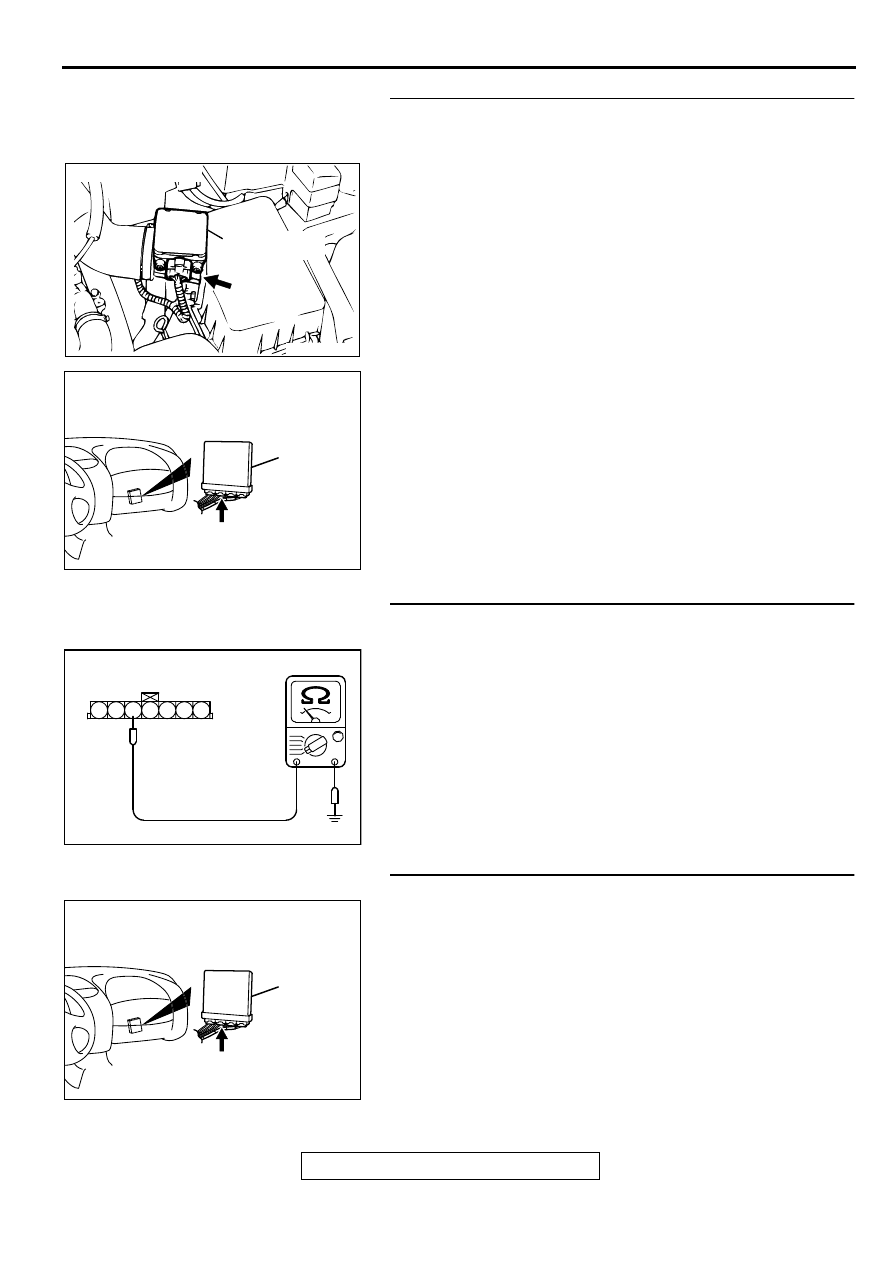
STEP 8. Check for short circuit to ground between volume 
air flow sensor connector B-14 terminal 3 and PCM 
connector C-40 terminal 65.
Q: Is the harness wire in good condition?

YES : Replace the PCM. Then go to Step 13.
NO :  Repair it. Then go to Step 13.

STEP 9. Check the continuity at volume air flow sensor 
harness side connector B-14.
(1) Disconnect the connector B-14 and measure at the harness 

side.

(2) Check for the continuity between terminal 5 and ground.

Should be less than 2 ohm.

Q: Is the continuity normal?

YES : Go to Step 12.
NO :  Go to Step 10.

STEP 10. Check connector C-40 at PCM for damage.
Q: Is the connector in good condition?

YES : Go to Step 11.
NO :  Repair or replace it. Refer to GROUP 00E, Harness 

Connector Inspection(

P.00E-2

). Then go to Step 13.

ACX02480

CONNECTOR : B-14

AC

VOLUME AIR
FLOW SENSOR

AK000280

CONNECTOR : C-40

PCM

AV

AKX01409AC

B-14 HARNESS
SIDE CONNECTOR

7 6 5 4 3 2 1

AK000280

CONNECTOR : C-40

PCM

AV

MULTIPORT FUEL INJECTION(MFI) DIAGNOSIS

TSB Revision

MULTIPORT FUEL INJECTION (MFI) <3.0L>

13B-30

STEP 11. Check for open circuit and harness damage 
between volume air flow sensor connector B-14 terminal 5 
and PCM connector C-40 terminal 57.
Q: Is the harness wire in good condition?

YES : Replace the PCM. Then go to Step 13.
NO :  Repair it. Then go to Step 13.

STEP 12. Check connector C-40 at PCM for damage.
Q: Is the connector in good condition?

YES : Replace the volume air flow sensor. Then go to Step 

13. 

NO :  Repair or replace it. Refer to GROUP 00E, Harness 

Connector Inspection(

P.00E-2

). Then go to Step 13.

STEP 13. Test the OBD-II drive cycle.
(1) Carry out a test drive with the drive cycle pattern. Refer to 

P.13B-4

, Procedure 6 

 Other Monitor.

(2) Check the diagnostic trouble code (DTC).

Q: Is the DTC P0101 is output?

YES : Retry the troubleshooting.
NO :  The inspection is complete.

ACX02480

CONNECTOR : B-14

AC

VOLUME AIR
FLOW SENSOR

AK000280

CONNECTOR : C-40

PCM

AV

AK000280

CONNECTOR : C-40

PCM

AV

MULTIPORT FUEL INJECTION(MFI) DIAGNOSIS

TSB Revision

MULTIPORT FUEL INJECTION (MFI) <3.0L>

13B-31

DTC P0102: Volume Air Flow Circuit Low Input

AK000496

1 2 3 4 5 6 7

RED

RED-

WHITE

RED-

WHITE

3 4

1 2

RED-

WHITE

GREEN-BLUE

BLA

CK

WHITE-GREEN

B-14

BATTERY

VOLUME AIR
FLOW SENSOR

5V

19

7

4

5

3

POWERTRAIN CONTROL
MODULE(PCM)

A-21X

MFI
RELAY

3

4

1

2

57

65

      C-39
(MU803784)

      C-40
(MU803781)

2

3 4

5 6

7 8

9

11 12 13 14 15 16 17 18 19 20

30

21 22 23

24 25

26 27 28 29

3132 33

34 35

1

10

42 43
48 49 50 51 52 53 54 55 56 57

46

45

44

58 59

60 61 62 63

64 65 66

47

41

MULTIPORT FUEL INJECTION(MFI) DIAGNOSIS

TSB Revision

MULTIPORT FUEL INJECTION (MFI) <3.0L>

13B-32

CIRCUIT OPERATION

The volume air flow sensor power is supplied 
from the MFI relay (terminal 1), and the ground is 
provided on the PCM (terminal 57).

5-volt power is applied to the volume air flow 
sensor output terminal (terminal 3) from the PCM 
(terminal 65). The volume air flow sensor 
generates a pulse signal when the output 
terminal and ground are opened/closed (opened/
short).

TECHNICAL DESCRIPTION

While the engine is running, the volume air flow 
sensor outputs a pulse signal which corresponds 
to the volume of air flow.

The PCM checks whether the frequency of this 
signal output by the volume air flow sensor while 
the engine is running is at or above the set value.

DTC SET CONDITIONS

Check Conditions

Throttle position sensor voltage is 1.5 volts or 
higher.

Engine speed is higher than 2,000 r/min.

Judgement Criteria

Volume air flow sensor output frequency has 
continued to be 60 Hz or lower for 2 seconds.

TROUBLESHOOTING HINTS (The most likely 
causes for this code to be set are:)

Volume air flow sensor failed.

Open or shorted volume air flow sensor circuit, or 
loose connector.

PCM failed.

Air leak between volume air flow sensor and 
throttle body.

DIAGNOSIS

Required Special Tools
MB991502: Scan Tool (MUT-II)

ACX02480

CONNECTOR : B-14

AC

VOLUME AIR
FLOW SENSOR

AK000555AB

CONNECTOR : A-21X

MFI RELAY

AK000280

CONNECTORS : C-39, C-40

C-39 C-40

PCM

AU


Content   ..  199  200  201  202   ..