Mitsubishi Galant. Manual - part 135


  Index      Mitsubishi     Mitsubishi Galant - service repair manual 2001 year


Search            


Content   ..  133  134  135  136   ..


Mitsubishi Galant. Manual - part 135


MULTIPORT FUEL INJECTION(MFI) DIAGNOSIS

TSB Revision

MULTIPORT FUEL INJECTION (MFI) <2.4L>

13A-221

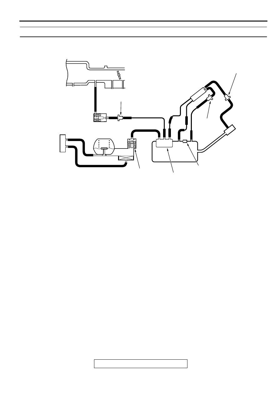
DTC P0450: Evaporative Emission Control System Pressure Sensor Malfunction

AC001943

A

B

C

EVAPORATIVE EMISSION 
PURGE SOLENOID

EVAPORATIVE 
EMISSION CANISTER

EVAPORATIVE 
EMISSION 
VENTILATION 
SOLENOID

FUEL TANK

CHECK VALVE A

CHECK 
VALVE B

INTAKE MANIFOLD

SYSTEM DIAGRAM

D

E

F

G

I

H

L

N

M

K

J

O

P

CHAMBER

AC

FUEL TANK DIFFRENTIAL 
PRESSURE SENSOR

MULTIPORT FUEL INJECTION(MFI) DIAGNOSIS

TSB Revision

MULTIPORT FUEL INJECTION (MFI) <2.4L>

13A-222

Fuel Tank Differential Pressure Sensor Circuit

MULTIPORT FUEL INJECTION(MFI) DIAGNOSIS

TSB Revision

MULTIPORT FUEL INJECTION (MFI) <2.4L>

13A-223

CIRCUIT OPERATION

A 5-volt voltage is supplied to the power terminal 
of the fuel tank differential pressure sensor 
(terminal 3) from the PCM (terminal 46). The 
ground terminal (terminal 2) is grounded with the 
PCM (terminal 57.)

A voltage proportional to the pressure in the fuel 
tank is sent from the output terminal of the fuel 
tank differential pressure sensor (terminal 1) to 
the PCM (terminal 92.)

TECHNICAL DESCRIPTION

To judge if the fuel tank differential pressure 
sensor is defective, the PCM monitors the fuel 
tank differential pressure sensor output voltage.

There are three different sets (A, B, C) of test 
conditions and the judgment criteria. Based on 
these test conditions and judgment criteria, the 
PCM judges if the fuel tank differential pressure 
sensor output voltage is normal.

NOTE: In rare cases, this DTC may be also set 
under some fuel and driving conditions regardless of 
the fuel pressure sensor output voltage when the fuel 
system is clogged.

DTC SET CONDITIONS

Test Conditions: Electrical noise

Idle switch: ON

Vehicle speed is 1.5 km/h (0.93 mph) or less.

Test Conditions: Judgment Criteria

The PCM looks for rapid voltage changes 
(electrical noise) equal to 20 or more spikes of 
0.2 volts or more in 25 millisecond averaged 
blocks.

The PCM must see this activity during 8 
consecutive idling periods from engine starting.

AC005041AB

CONNECTOR:C-17

AC005043

CONNECTORS : C-40, C-41

C-41

C-40

PCM

AB

AC005042 AB

CONNECTOR:C-71

AC002041AC

CONNECTOR: D-11

FUEL TANK DIFFERENTIAL 
PRESSURE SENSOR

AC005044 AB

CONNECTOR:D-15

MULTIPORT FUEL INJECTION(MFI) DIAGNOSIS

TSB Revision

MULTIPORT FUEL INJECTION (MFI) <2.4L>

13A-224

NOTE: Rapid voltage occurs due to fuel sloshing 
during refuelling. However, when the PCM sees 
the activity mentioned above 8 consecutive 
times, it judges that an electrical noise is present.

NOTE: The PCM determines that the engine is 
not idling if all of the following conditions are met.

.

Engine speed is higher than 2,500 r/min.

Vehicle speed is 15 km/h (9.3 mph) or more.

Volumetric efficiency is 55 percent or more.

TROUBLESHOOTING HINTS
The most likely causes for this code to be set are:

Fuel tank differential pressure sensor failed.

Open or shorted fuel tank differential pressure 
sensor circuit, or loose connector.

PCM failed.

Blockage of evaporative emission system 
(causing high pressure.)

OVERVIEW OF TROUBLESHOOTING

The DTC P0450 can be set if either of the 
following conditions occur:

1. Faulty fuel differential pressure sensor, 

related circuit, or PCM.

2. Faulty fuel filler neck evaporative emission 

ventilation solenoid or blocked vapor line.

To check a system blockage, do a performance 
test which uses a mechanical vacuum gauge and 
the scan tool MB991502 set on the fuel tank 
differential pressure sensor (TANK PRS 
SNSR73.)
The mechanical gauge reading is used to verify 
the scan tool MB991502 reading.
A comparison of the mechanical gauge to the 
scan tool MB991502 determines the problem in 
the system.

DIAGNOSIS

Required Special Tools:

MB991502: Scan Tool (MUT-II)

MB991658: Test Harness Set

STEP 1. Using scan tool MB991502, check data list item 73: 
Fuel Tank Differential Pressure Sensor.

CAUTION

To prevent damage to scan tool MB991502, always turn the 
ignition switch to "LOCK" (OFF) position before 
connecting or disconnecting scan tool MB991502.
(1) Connect scan tool MB991502 to the data link connector.
(2) Turn the ignition switch to the "ON" position.
(3) Remove the fuel cap.
(4) Set scan tool MB991502 to the data reading mode for item 

73, Fuel Tank Differential Pressure Sensor.

The fuel tank pressures should be -1.5 to 1.5kPa.

(5) Connect an evaporative emission system pressure pump to 

the fuel filler neck, and apply pressure.

The scan tool reading should increase.

Q: Is the scan tool reading within the specified value?

YES : Go to Step 20.
NO :  Go to Step 2.

AC003081 AB

16 PIN

MB991502

AC000186


Content   ..  133  134  135  136   ..