Mitsubishi Galant. Manual - part 95


  Index      Mitsubishi     Mitsubishi Galant - service repair manual 2001 year


Search            


Content   ..  93  94  95  96   ..


Mitsubishi Galant. Manual - part 95


MULTIPORT FUEL INJECTION(MFI) DIAGNOSIS

TSB Revision

MULTIPORT FUEL INJECTION (MFI) <2.4L>

13A-61

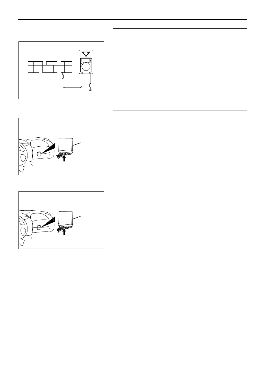
STEP 8. Check the sensor supply voltage at PCM 
connector C-40 by backprobing.
(1) Do not disconnect the PCM connector C-40.
(2) Disconnect the intake air temperature sensor connector B-

14.

(3) Turn the ignition switch to the "ON" position.
(4) Measure the voltage between terminal 64 and ground by 

backprobing.

Voltage should be between 4.5 and 4.9 volts.

(5) Turn the ignition switch to the "LOCK" (OFF) position.

Q: Is the voltage normal?

YES : Go to Step 9.
NO :  Go to Step 10.

STEP 9. Check connector C-40 at PCM for damage.
Q: Is the connector in good condition?

YES : Repair harness wire between intake air temperature 

sensor connector B-14 terminal 6 and PCM connector 
C-40 terminal 64 because of open circuit. Then go to 
Step 19.

NO :  Repair or replace it. Refer to GROUP 00E, Harness 

Connector Inspection(

P.00E-2

). Then go to Step 19.

STEP 10. Check connector C-40 at PCM for damage.
Q: Is the connector in good condition?

YES : Go to Step 11.
NO :  Repair or replace it. Refer to GROUP 00E, Harness 

Connector Inspection(

P.00E-2

). Then go to Step 19.

AK000286

C-40 CONNECTOR
HARNESS SIDE VIEW

46
57
66

45
56
65

44
55

43
49

54

64

42
48
59

41
47
58

53
63

52
62

51
61

50
60

AC

AK000280

CONNECTOR : C-40

PCM

AV

AK000280

CONNECTOR : C-40

PCM

AV

MULTIPORT FUEL INJECTION(MFI) DIAGNOSIS

TSB Revision

MULTIPORT FUEL INJECTION (MFI) <2.4L>

13A-62

STEP 11. Check for short circuit to ground between intake 
air temperature sensor connector B-14 terminal 6 and PCM 
connector C-40 terminal 64.
Q: Is the harness wire in good condition?

YES : Replace the PCM. Then go to Step 19.
NO :  Repair it. Then go to Step 19.

STEP 12. Check the continuity at intake air temperature 
sensor harness side connector B-14.
(1) Disconnect the connector B-14 and measure at the harness 

side.

(2) Check for the continuity between terminal 5 and ground.

Should be less than 2 ohm.

Q: Is the continuity normal?

YES : Go to Step 15.
NO :  Go to Step 13.

STEP 13. Check connector C-40 at PCM for damage.
Q: Is the connector in good condition?

YES : Go to Step 14.
NO :  Repair or replace it. Refer to GROUP 00E, Harness 

Connector Inspection(

P.00E-2

). Then go to Step 19.

ACX02480

CONNECTOR : B-14

AG

INTAKE AIR
TEMPERATURE
SENSOR

AK000280

CONNECTOR : C-40

PCM

AV

AKX01409AC

B-14 HARNESS
SIDE CONNECTOR

7 6 5 4 3 2 1

AK000280

CONNECTOR : C-40

PCM

AV

MULTIPORT FUEL INJECTION(MFI) DIAGNOSIS

TSB Revision

MULTIPORT FUEL INJECTION (MFI) <2.4L>

13A-63

STEP 14. Check for open circuit and harness damage 
between intake air temperature sensor connector B-14 
terminal 5 and PCM connector C-40 terminal 57.
Q: Is the harness wire in good condition?

YES : Replace the PCM. Then go to Step 19.
NO :  Repair it. Then go to Step 19.

ACX02480

CONNECTOR : B-14

AG

INTAKE AIR
TEMPERATURE
SENSOR

AK000280

CONNECTOR : C-40

PCM

AV

MULTIPORT FUEL INJECTION(MFI) DIAGNOSIS

TSB Revision

MULTIPORT FUEL INJECTION (MFI) <2.4L>

13A-64

STEP 15. Check the intake air temperature sensor.
(1) Disconnect the intake air temperature sensor connector B-

14

(2) Measure the resistance between intake air temperature 

sensor side connector terminal 5 and 6.

(3) Measure resistance while heating the sensor using a hair 

drier.

Standard value:

5.3 

−−−−

 6.7 k

 [at 0

°°°°

 C (32

°°°°

 F)]

2.3 

−−−−

 3.0 k

 [at 20

°°°°

 C (68

°°°°

 F)]

1.0 

−−−−

 1.5 k

 [at 40

°°°°

 C (104

°°°°

 F)]

0.30 

−−−−

 0.42 k

 [at 80

°°°°

 C (176

°°°°

 F)]

Q: Is the resistance at the standard value?

YES : Go to Step 16.
NO :  Replace the volume air flow sensor. Then go to Step 

19.

STEP 16. Check connector C-40 at PCM for damage.
Q: Is the connector in good condition?

YES : Go to Step 17.
NO :  Repair or replace it. Refer to GROUP 00E, Harness 

Connector Inspection(

P.00E-2

). Then go to Step 19.

ACX02480

CONNECTOR : B-14

AG

INTAKE AIR
TEMPERATURE
SENSOR

AK000319AB

1 2 3 4 5 6 7

INTAKE AIR TEMPERATURE
SENSOR SIDE CONNECTOR

AKX01621 AB

INTAKE AIR
TEMPERATURE
SENSOR

AK000280

CONNECTOR : C-40

PCM

AV


Content   ..  93  94  95  96   ..