Mitsubishi Galant 9G. Manual - part 997


  Index      Mitsubishi     Mitsubishi Galant 9G - service repair manual


Search            


Content   ..  995  996  997  998   ..


Mitsubishi Galant 9G. Manual - part 997


MULTIPORT FUEL INJECTION (MFI) DIAGNOSIS

TSB Revision

MULTIPORT FUEL INJECTION (MFI) <3.8L ENGINE>

13B-288

OBD-II DRIVE CYCLE PATTERN

Refer to Diagnostic Function 

− OBD-II Drive Cycle − 

Procedure 4 

− Heated Oxygen Sensor Monitor 

P.13B-6

.

.

TROUBLESHOOTING HINTS (The most 
likely causes for this code to be set are: )

• Right bank heated oxygen sensor (rear) failed.

• Connector damage.

• PCM failed.

DIAGNOSIS

Required Special Tools:

• MB991958: Scan Tool (MUT-III Sub Assembly)

• MB991824: V.C.I.

• MB991827: USB Cable

• MB991910: Main Harness A

• MB991316: Test Harness

STEP 1. Using scan tool MB991958, check data list item 69: 
Heated Oxygen Sensor Bank 1, Sensor 2 (right rear).

CAUTION

To prevent damage to scan tool MB991958, always turn the 
ignition switch to the "LOCK" (OFF) position before con-
necting or disconnecting scan tool MB991958.
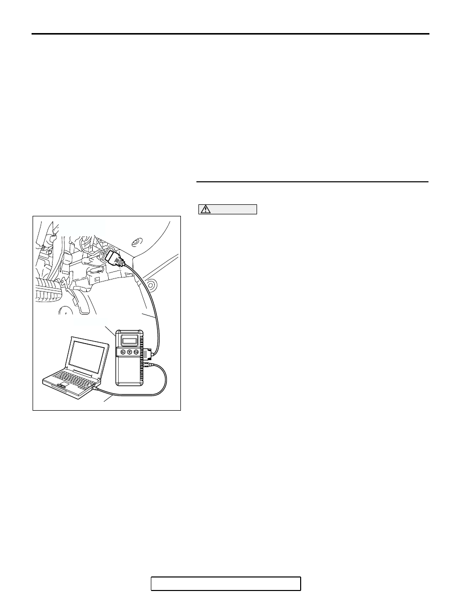
(1) Connect scan tool MB991958 to the data link connector.
(2) Start the engine and run at idle.

(3) Set scan tool MB991958 to the data reading mode for item 

69, Heated Oxygen Sensor Bank 1, Sensor 2 (right rear).

(4) Warm up the engine.

• After increasing the output voltage 0.15 volt or more by 

the engine revving, finish it. Then confirm that the output 
voltage reduces to 0.15 volt or less within 3 seconds.

(5) Turn the ignition switch to the "LOCK" (OFF) position.
Q: Is the sensor operating properly?

YES : It can be assumed that this malfunction is intermittent. 

Refer to GROUP 00, How to Use 
Troubleshooting/Inspection Service Points 

− How to 

Cope with Intermittent Malfunctions 

P.00-14

.

NO :  Replace the heated oxygen sensor (rear). Then go to 

Step 2. 

AC305412

AB

MB991910

DATA LINK

CONNECTOR

MB991824

MB991827

MULTIPORT FUEL INJECTION (MFI) DIAGNOSIS

TSB Revision

MULTIPORT FUEL INJECTION (MFI) <3.8L ENGINE>

13B-289

STEP 2. Check the right bank heated oxygen sensor (rear).

(1) Disconnect the right bank heated oxygen sensor (rear) 

connector B-08 and connect test harness special tool, 
MB991316, to the connector on the right bank heated 
oxygen sensor (rear) side.

(2) Warm up the engine until engine coolant temperature 

reaches 80

°C (176°F) or higher.

(3) Perform a racing for 5 minutes or more with the engine 

speed of 4,500 r/min.

(4) Connect a digital voltage meter between terminal No. 2 

(black clip) and terminal No. 4 (white clip).

(5) While repeatedly revving the engine, measure the right 

bank heated oxygen sensor (rear) output voltage.

Standard value: 0.6 

 1.0 volt

CAUTION

• Be very careful when connecting the jumper wires; 

incorrect connection can damage the heated oxygen 
sensor.

• Be careful the heater is broken when voltage of beyond 

8 volts is applied to the heated oxygen sensor heater.
NOTE: If the sufficiently high temperature [of approximate 
400

°

C (752

°

F) or more] is not reached although the heated 

oxygen sensor is normal, the output voltage would be possi-
bly low although the rich air/fuel ratio. Therefore, if the out-
put voltage is low, use a jumper wire to connect the terminal 
No.1 (red clip) and the terminal No. 3 (blue clip) of the 
heated oxygen sensor with the positive terminal and the 
negative terminal of 8 volts power supply respectively, then 
check again.

Q: Is the voltage between 0.6 and 1.0 volt?

YES : Go to Step 3.
NO :  Replace the right bank heated oxygen sensor (rear). 

Then go to Step 4.

AK303064

1

2

3

4

THROTTLE BODY

RIGHT BANK
HEATED OXYGEN
SENSOR (REAR)

CONNECTOR: B-08

B-08 (GR)

AB

HARNESS
CONNECTOR:
COMPONENT SIDE

AKX01624

HEATED
OXYGEN
SENSOR
COMPONENT
SIDE
CONNECTOR

MB991316

WHITE

BLACK

AN

MULTIPORT FUEL INJECTION (MFI) DIAGNOSIS

TSB Revision

MULTIPORT FUEL INJECTION (MFI) <3.8L ENGINE>

13B-290

STEP 3. Check harness connector B-08 at right bank 
heated oxygen sensor (rear) and harness connector B-21, 
B-22 at PCM for damage.

Q: Is the harness connector in good condition?

YES : Replace the PCM.Then go to Step 4.
NO :  Repair or replace it. Refer to GROUP 00E, Harness 

Connector Inspection 

P.00E-2

. Then go to Step 4.

AK303064

1

2

3

4

THROTTLE BODY

RIGHT BANK
HEATED OXYGEN
SENSOR (REAR)

CONNECTOR: B-08

B-08 (GR)

AB

HARNESS
CONNECTOR:
COMPONENT SIDE

AK303052

55

56

54 53 52 51

57

62 61 60 59 58

63

69 68 67 66 65 64

70

75 74 73 72 71

76

82 81 80 79 78 77

83

104

96

94

95

93 92 91

99 98 97

103 102 101 100

108 107 106 105

113 112 111 110 109

CONNECTORS: B-21, B-22

AB

B-21 HARNESS CONNECTOR: 
COMPONENT SIDE

B-22 HARNESS CONNECTOR: 
COMPONENT SIDE

PCM

AIR CLEANER

B-22 (B)

B-21 (B)

MULTIPORT FUEL INJECTION (MFI) DIAGNOSIS

TSB Revision

MULTIPORT FUEL INJECTION (MFI) <3.8L ENGINE>

13B-291

STEP 4. Test the OBD-II drive cycle.

(1) Carry out a test drive with the drive cycle pattern. Refer to 

Diagnostic Function 

− OBD-II Drive Cycle − Procedure 4 − 

Heated Oxygen Sensor Monitor 

P.13B-6

.

(2) Check the diagnostic trouble code (DTC).
Q: Is DTC P0139 set?

YES : Retry the troubleshooting.
NO :  The inspection is complete.

DTC P0141: Heated Oxygen Sensor Heater Circuit (bank 1, sensor 2)

RED-

WHITE

AK400902

BR

O

W

N-BLA

CK

RIGHT BANK HEATED
OXYGEN SENSOR (REAR)

B-17X

1

2

3

4

BATTERY

1

3

2

4

138

MFI
RELAY

POWERTRAIN
CONTROL
MODULE (PCM)

B-08

MU802665

Right Bank Heated Oxygen Sensor (rear) Heater Circuit

B-23

RED-

WHITE

1

2

3

4

121 122 123 124 125 126 127

128 129 130 131 132 133

134 135 136 137 138 139 140

141 142 143 144 145 146

147 148 149 150 151 152 153

RED

RED-WHITE

TO PCM

TO PCM TO PCM

1

2

3

4


Content   ..  995  996  997  998   ..