Mitsubishi Galant 9G. Manual - part 985


  Index      Mitsubishi     Mitsubishi Galant 9G - service repair manual


Search            


Content   ..  983  984  985  986   ..


Mitsubishi Galant 9G. Manual - part 985


MULTIPORT FUEL INJECTION (MFI) DIAGNOSIS

TSB Revision

MULTIPORT FUEL INJECTION (MFI) <3.8L ENGINE>

13B-240

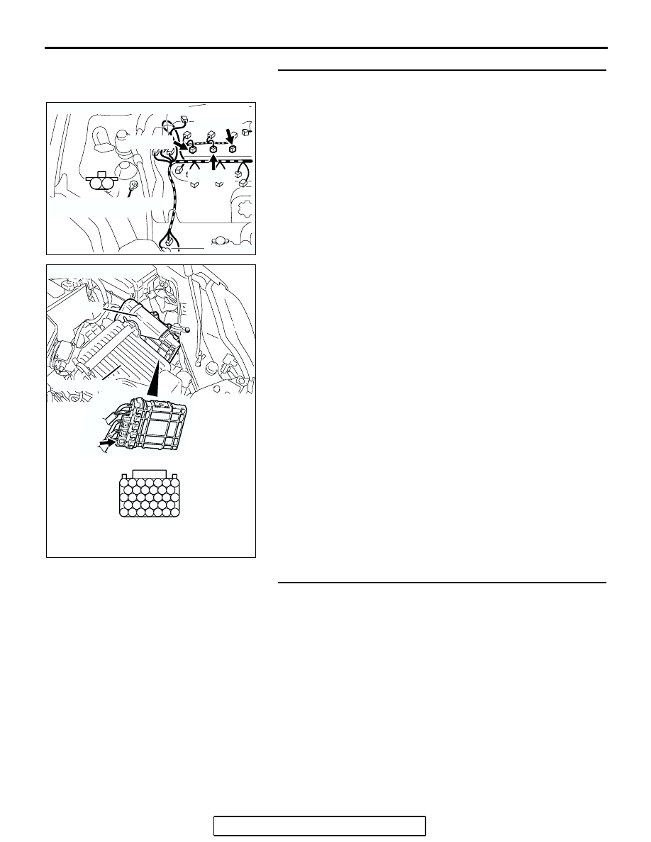
STEP 12. Check for harness damage between right bank 
injector connector and PCM connector.

a. Check the harness wire between right bank injector connec-

tor B-01 (terminal No. 2) and PCM connector B-23 (terminal 
No. 153) when checking No. 1 cylinder.

b. Check the harness wire between right bank injector connec-

tor B-03 (terminal No. 2) and PCM connector B-23 (terminal 
No. 140) when checking No. 3 cylinder.

c. Check the harness wire between right bank injector connec-

tor B-04 (terminal No. 2) and PCM connector B-23 (terminal 
No. 133) when checking No. 5 cylinder.

Q: Is the harness wire in good condition?

YES : Go to Step 13.
NO :  Repair it. Then go to Step 14.

STEP 13. Check the fuel pressure.

Refer to On-vehicle Service 

− Fuel Pressure Test 

P.13B-1179

.

Q: Is the fuel pressure normal?

YES : Replace the PCM. Then go to Step 14.
NO :  Repair it. Then go to Step 14.

AK303055

M

1

2

CONNECTOR: B-01, B-03, B-04

AB

B-01 (GR)

B-03 (GR)

B-04 (GR)

HARNESS CONNECTOR:
COMPONENT SIDE

127 126 125 124 123 122 121

133 132 131 130 129 128

140 139 138 137 136 135 134

146 145 144 143 142 141

153 152 151 150 149 148 147

AK303058

HARNESS CONNECTOR: 
COMPONENT SIDE

CONNECTOR: B-23

B-23

PCM

AB

AIR CLEANER

MULTIPORT FUEL INJECTION (MFI) DIAGNOSIS

TSB Revision

MULTIPORT FUEL INJECTION (MFI) <3.8L ENGINE>

13B-241

STEP 14. Test the OBD-II drive cycle.
(1) Carry out a test drive with the drive cycle pattern. Refer to 

Diagnostic Function 

− OBD-II Drive Cycle − Procedure 6 − 

Other Monitor 

P.13B-6

.

(2) Check the diagnostic trouble code (DTC).
Q: Is DTC P0134 set?

YES : Retry the troubleshooting.
NO :  The inspection is complete.

DTC P0135: Heated Oxygen Sensor Heater Circuit (bank 1, sensor 1)

RED-

WHITE

RED

AK400901

RED-WHITE

WHITE-BLA

CK

RIGHT BANK HEATED
OXYGEN SENSOR (FRONT)

B-17X

1

2

3

4

BATTERY

1

3

2

4

126

MFI
RELAY

B-09

MU802605

POWERTRAIN
CONTROL
MODULE (PCM)

Right Bank Heated Oxygen Sensor (front) Heater Circuit

B-23

RED-

WHITE

1

2

3

4

121 122 123 124 125 126 127

128 129 130 131 132 133

134 135 136 137 138 139 140

141 142 143 144 145 146

147 148 149 150 151 152 153

1

2

3

4

TO PCM

TO PCM TO PCM

MULTIPORT FUEL INJECTION (MFI) DIAGNOSIS

TSB Revision

MULTIPORT FUEL INJECTION (MFI) <3.8L ENGINE>

13B-242

.

CIRCUIT OPERATION

• Power is supplied from the MFI relay (terminal 

No. 4) to the right bank heated oxygen sensor 

(front) heater.

• The PCM (terminal No. 126) controls continuity to 

the right bank heated oxygen sensor (front) 

heater by turning the power transistor in the PCM 

"ON" and "OFF".

.

TECHNICAL DESCRIPTION

• The PCM checks whether the heater current is 

within a specified range when the heater is ener-

gized.

.

DESCRIPTIONS OF MONITOR METHODS

Right bank heated oxygen sensor heater (front) cur-

rent is out of specified range when engine coolant 

temperature is over 20

°C (68°F).

.

MONITOR EXECUTION

Continuous

.

MONITOR EXECUTION CONDITIONS 
(Other monitor and Sensor)

Other Monitor (There is no temporary DTC stored 

in memory for the item monitored below)

• Not applicable

Sensor (The sensor below is determined to be 

normal)

• Engine coolant temperature sensor

.

1

2

3

4

1

2

3

4

1

2

3

4

1

2

3

4

AK303014

CONNECTOR: B-17X

MFI RELAY

MFI RELAY

FRONT OF VEHICLE

B-17X

AB

AK303059

CONNECTOR: B-23

PCM

AB

AIR CLEANER

B-23

AK303047

B-09 (B)

CONNECTOR: B-09

THROTTLE BODY

RIGHT BANK
HEATED OXYGEN
SENSOR (FRONT)

AB

MULTIPORT FUEL INJECTION (MFI) DIAGNOSIS

TSB Revision

MULTIPORT FUEL INJECTION (MFI) <3.8L ENGINE>

13B-243

DTC SET CONDITIONS

Logic Flow Chart

.

Check Conditions

• 60 seconds have elapsed from the start of the 

previous monitoring.

• Engine coolant temperature is higher than 20°C 

(68

°F).

• While the right bank heated oxygen sensor (front) 

heater is on.

• Battery positive voltage is between 11 and 16.5 

volts.

Judgment Criteria

• The right bank heated oxygen sensor (front) 

heater current has continued to be lower than 
0.16 ampere or higher than 7.5 ampere for 4 sec-
onds.

.

OBD-II DRIVE CYCLE PATTERN

Refer to Diagnostic Function 

− OBD-II Drive Cycle − 

Procedure 6 

− Other Monitor 

P.13B-6

.

.

TROUBLESHOOTING HINTS (The most 
likely causes for this code to be set are: )

• Open or shorted right bank heated oxygen sen-

sor (front) heater circuit, harness damage, or 
connector damage.

• Open circuit in right bank heated oxygen sensor 

(front) heater.

• PCM failed.

START

END

YES

YES

YES

YES

NO

NO

NO

NO

MALFUNCTION

GOOD

CONTINUOUS

FAILURE FOR 4secs

MONITORING

CONDITIONS

CURRENT < 0.16A

CURRENT > 7.5A

AK302400


Content   ..  983  984  985  986   ..