Mitsubishi Galant 9G. Manual - part 967


  Index      Mitsubishi     Mitsubishi Galant 9G - service repair manual


Search            


Content   ..  965  966  967  968   ..


Mitsubishi Galant 9G. Manual - part 967


MULTIPORT FUEL INJECTION (MFI) DIAGNOSIS

TSB Revision

MULTIPORT FUEL INJECTION (MFI) <3.8L ENGINE>

13B-168

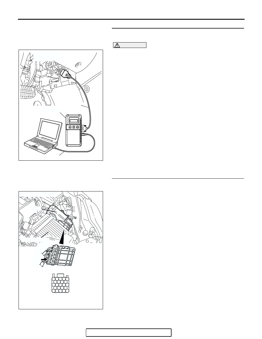
STEP 6. Using scan tool MB991958, check data list item 79: 
Throttle Position Sensor (main).

CAUTION

To prevent damage to scan tool MB991958, always turn the 
ignition switch to the "LOCK"(OFF) position before con-
necting or disconnecting scan tool MB991958.
(1) Connect scan tool MB991958 to the data link connector.
(2) Turn the ignition switch to the "ON" position.
(3) Detach the intake air hose at the throttle body.
(4) Disconnect the connector of the throttle position sensor.
(5) Use test harness special tool (MB991658) to connect only 

terminals No. 3, No. 4, No. 5, and No. 6.

(6) Set scan tool MB991958 to the data reading mode for item 

79, Throttle Position Sensor (main).

• Output voltage should be between 0.3 and 0.7 volt when 

the throttle valve is fully closed with your finger.

• Output voltage should be 4.0 volts or more when the 

throttle valve is fully open with your finger.

(7) Turn the ignition switch to the "LOCK"(OFF) position.
Q: Is the sensor operating properly?

YES : It can be assumed that this malfunction is intermittent. 

Refer to GROUP 00, How to Use 
Troubleshooting/Inspection Service Points 

− How to 

Cope with Intermittent Malfunctions 

P.00-14

.

NO :  Replace the PCM. Then go to Step 11.

STEP 7. Check harness connector B-22 at PCM for 
damage.

Q: Is the harness connector in good condition?

YES : Go to Step 8.
NO :  Repair or replace it. Refer to GROUP 00E, Harness 

Connector Inspection 

P.00E-2

. Then go to Step 11.

AC305412

AB

MB991910

DATA LINK

CONNECTOR

MB991824

MB991827

AK303016

104

96

94

95

93 92 91

99 98 97

103 102 101 100

108 107 106 105

113 112 111 110 109

CONNECTOR: B-22

B-22 (B)

PCM

AB

HARNESS CONNECTOR: 
COMPONENT SIDE

AIR CLEANER

MULTIPORT FUEL INJECTION (MFI) DIAGNOSIS

TSB Revision

MULTIPORT FUEL INJECTION (MFI) <3.8L ENGINE>

13B-169

STEP 8. Check for harness damage between throttle 
position sensor connector B-06 (terminal No. 5) and PCM 
connector B-22 (terminal No. 94).

Q: Is the harness wire in good condition?

YES : Go to Step 9.
NO :  Repair it. Then go to Step 11.

2 1

6 5 4 3

AK303044

HARNESS
CONNECTOR:
COMPONENT SIDE

B-06 (B)

CONNECTOR: B-06

AB

AK303016

104

96

94

95

93 92 91

99 98 97

103 102 101 100

108 107 106 105

113 112 111 110 109

CONNECTOR: B-22

B-22 (B)

PCM

AB

HARNESS CONNECTOR: 
COMPONENT SIDE

AIR CLEANER

MULTIPORT FUEL INJECTION (MFI) DIAGNOSIS

TSB Revision

MULTIPORT FUEL INJECTION (MFI) <3.8L ENGINE>

13B-170

STEP 9. Check for open circuit, short circuit to ground and 
harness damage between throttle position sensor 
connector B-06 (terminal No. 6) and PCM connector B-22 
(terminal No. 98).

Q: Is the harness wire in good condition?

YES : Go to Step 10.
NO :  Repair it. Then go to Step 11.

STEP 10. Replace the throttle body assembly.

(1) Replace the throttle body assembly.
(2) Turn the ignition switch to the "ON" position.

(3) After the DTC has been deleted, read the DTC again.
(4) Turn the ignition switch to the "LOCK" (OFF) position.
Q: Is DTC P0122 set?

YES : Replace the PCM. Then go to Step 11.
NO :  The inspection is complete.

2 1

6 5 4 3

AK303044

HARNESS
CONNECTOR:
COMPONENT SIDE

B-06 (B)

CONNECTOR: B-06

AB

AK303016

104

96

94

95

93 92 91

99 98 97

103 102 101 100

108 107 106 105

113 112 111 110 109

CONNECTOR: B-22

B-22 (B)

PCM

AB

HARNESS CONNECTOR: 
COMPONENT SIDE

AIR CLEANER

2 1

6 5 4 3

AK303044

HARNESS
CONNECTOR:
COMPONENT SIDE

B-06 (B)

CONNECTOR: B-06

AB

MULTIPORT FUEL INJECTION (MFI) DIAGNOSIS

TSB Revision

MULTIPORT FUEL INJECTION (MFI) <3.8L ENGINE>

13B-171

STEP 11. Using scan tool MB991958, read the diagnostic 
trouble code (DTC).

CAUTION

To prevent damage to scan tool MB991958, always turn the 
ignition switch to the "LOCK"(OFF) position before con-
necting or disconnecting scan tool MB991958.
(1) Connect scan tool MB991958 to the data link connector.
(2) Turn the ignition switch to the "ON" position.
(3) After the DTC has been deleted, read the DTC again.
(4) Turn the ignition switch to the "LOCK"(OFF) position.
Q: Is DTC P0122 set?

YES : Retry the troubleshooting.
NO :  The inspection is complete.

AC305412

AB

MB991910

DATA LINK

CONNECTOR

MB991824

MB991827


Content   ..  965  966  967  968   ..