Mitsubishi Galant 9G. Manual - part 954


  Index      Mitsubishi     Mitsubishi Galant 9G - service repair manual


Search            


Content   ..  952  953  954  955   ..


Mitsubishi Galant 9G. Manual - part 954


MULTIPORT FUEL INJECTION (MFI) DIAGNOSIS

TSB Revision

MULTIPORT FUEL INJECTION (MFI) <3.8L ENGINE>

13B-116

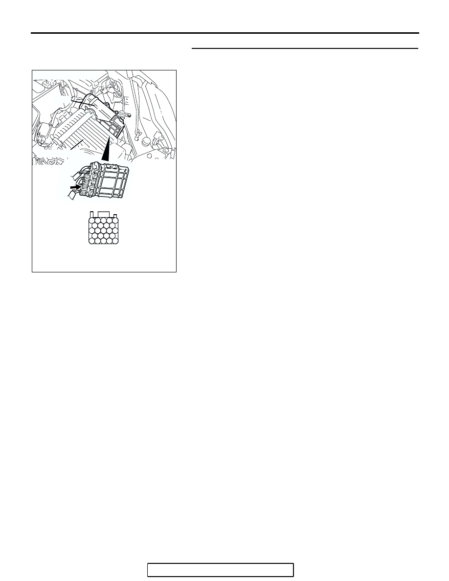
STEP 7. Check harness connector B-22 at PCM for 
damage.

Q: Is the harness connector in good condition?

YES : Go to Step 8.
NO :  Repair or replace it. Refer to GROUP 00E, Harness 

Connector Inspection 

P.00E-2

. Then go to Step 9.

AK303016

104

96

94

95

93 92 91

99 98 97

103 102 101 100

108 107 106 105

113 112 111 110 109

CONNECTOR: B-22

B-22 (B)

PCM

AB

HARNESS CONNECTOR: 
COMPONENT SIDE

AIR CLEANER

MULTIPORT FUEL INJECTION (MFI) DIAGNOSIS

TSB Revision

MULTIPORT FUEL INJECTION (MFI) <3.8L ENGINE>

13B-117

STEP 8. Check for open circuit and harness damage 
between intake air temperature sensor connector B-10 
(terminal No. 1) and PCM connector B-22 (terminal No. 
107).

Q: Is the harness wire in good condition?

YES : Replace the PCM. Then go to Step 9.
NO :  Repair it. Then go to Step 9.

STEP 9. Test the OBD-II drive cycle.
(1) Carry out a test drive with the drive cycle pattern. Refer to 

Diagnostic Function 

− OBD-II Drive Cycle − Procedure 6 − 

Other Monitor 

P.13B-6

.

(2) Check the diagnostic trouble code (DTC).
Q: Is DTC P0111 set?

YES : Retry the troubleshooting.
NO :  The inspection is complete.

AK303015

2

1

3

4

AB

B-10 (GR)

CONNECTOR: B-10

HARNESS
CONNECTOR:
COMPONENT SIDE

AK303016

104

96

94

95

93 92 91

99 98 97

103 102 101 100

108 107 106 105

113 112 111 110 109

CONNECTOR: B-22

B-22 (B)

PCM

AB

HARNESS CONNECTOR: 
COMPONENT SIDE

AIR CLEANER

MULTIPORT FUEL INJECTION (MFI) DIAGNOSIS

TSB Revision

MULTIPORT FUEL INJECTION (MFI) <3.8L ENGINE>

13B-118

DTC P0112: Intake Air Temperature Circuit Low Input

CAUTION

If DTC P0112 has been set, TCL related DTC 
U1120 is also set. After P0112 has been diag-
nosed, don't forget to erase DTC U1120.

.

100

99

92

91

93 94 95

96 97 98

101 102 103 104

105 106 107 108

109 110 111 112 113

52

51

53 54 55 56

57

58 59 60 61 62

63

64 65 66 67 68 69

70

71 72 73 74 75

76

77 78 79 80 81 82

83

1

2

3 4

AK303812

BLA

C

K

RED-BLUE

INTAKE AIR TEMPERATURE SENSOR
(INTEGRATED IN MASS AIRFLOW 
 SENSOR)

POWERTRAIN CONTROL MODULE (PCM)

5 V

107

4

69

1

B-10

Intake Air Temperature Sensor Circuit

B-21

B-22

AK303012

CONNECTOR: B-10

AC

B-10 (GR)

INTAKE AIR 
TEMPERATURE 
SENSOR 
(INTEGRATED IN 
MASS AIRFLOW 
SENSOR)

AK303013

CONNECTORS: B-21, B-22

PCM

AB

AIR CLEANER

B-22 (B)

B-21 (B)

MULTIPORT FUEL INJECTION (MFI) DIAGNOSIS

TSB Revision

MULTIPORT FUEL INJECTION (MFI) <3.8L ENGINE>

13B-119

CIRCUIT OPERATION

• Approximately 5 volts are applied to the intake air 

temperature sensor output terminal (terminal No. 
1) from the PCM (terminal No. 107) via the resis-
tor in the PCM. The ground terminal (terminal No. 
4) is grounded with PCM (terminal No. 69).

• The intake air temperature sensor is a negative 

temperature coefficient type of resistor. When the 
intake air temperature rises, the resistance 
decreases.

• The intake air temperature sensor output voltage 

increases when the resistance increases and 
decreases when the resistance decreases.

.

TECHNICAL DESCRIPTION

• The intake air temperature sensor converts the 

intake air temperature to a voltage.

• The PCM checks whether this voltage is within a 

specified range.

.

DESCRIPTIONS OF MONITOR METHODS

Intake air temperature sensor output voltage is out of 

specified range.

.

MONITOR EXECUTION

Continuous

.

MONITOR EXECUTION CONDITIONS 
(Other monitor and Sensor)

Other Monitor (There is no temporary DTC stored 

in memory for the item monitored below)

• Not applicable

Sensor (The sensor below is determined to be 

normal)

• Not applicable

.


Content   ..  952  953  954  955   ..