Mitsubishi Galant 9G. Manual - part 942
MULTIPORT FUEL INJECTION (MFI) DIAGNOSIS
TSB Revision
MULTIPORT FUEL INJECTION (MFI) <3.8L ENGINE>
13B-68
.
CIRCUIT OPERATION
• The mass airflow sensor power is supplied from
the MFI relay (terminal No. 4), and the ground is
provided on the PCM (terminal No. 69).
• 5-volt power is applied to the mass airflow sensor
output terminal (terminal No. 3) from the PCM
(terminal No. 108).
.
TECHNICAL DESCRIPTION
• While the engine is running, the mass airflow
sensor outputs voltage which corresponds to the
mass airflow rate.
• The PCM checks whether the voltage output by
the mass airflow sensor while the engine is run-
ning is within a specified range.
.
DESCRIPTIONS OF MONITOR METHODS
Mass airflow sensor output voltage is out of specified
range.
.
MONITOR EXECUTION
Continuous
.
MONITOR EXECUTION CONDITIONS
(Other monitor and Sensor)
Other Monitor (There is no temporary DTC stored
in memory for the item monitored below)
• Not applicable
Sensor (The sensor below is determined to be
normal)
• Not applicable
.
1
2
3
4
1
2
3
4
1
2
3
4
1
2
3
4
AK303014
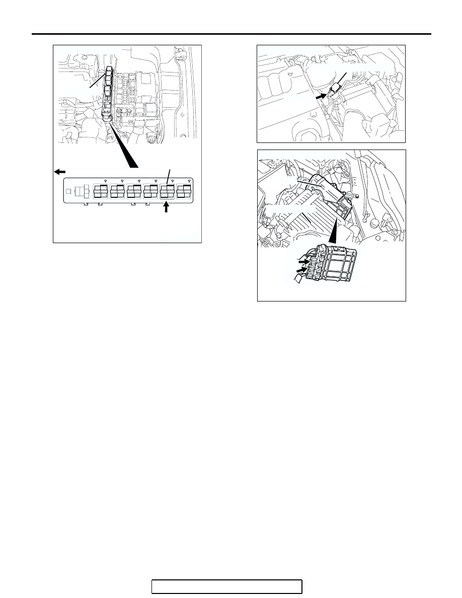
CONNECTOR: B-17X
MFI RELAY
MFI RELAY
FRONT OF VEHICLE
B-17X
AB
AK303012
CONNECTOR: B-10
MASS AIRFLOW SENSOR
AB
B-10 (GR)
AK303013
CONNECTORS: B-21, B-22
PCM
AB
AIR CLEANER
B-22 (B)
B-21 (B)