Mitsubishi Galant 9G. Manual - part 896


  Index      Mitsubishi     Mitsubishi Galant 9G - service repair manual


Search            


Content   ..  894  895  896  897   ..


Mitsubishi Galant 9G. Manual - part 896


MULTIPORT FUEL INJECTION (MFI) DIAGNOSIS

TSB Revision

MULTIPORT FUEL INJECTION (MFI) <2.4L ENGINE>

13A-1026

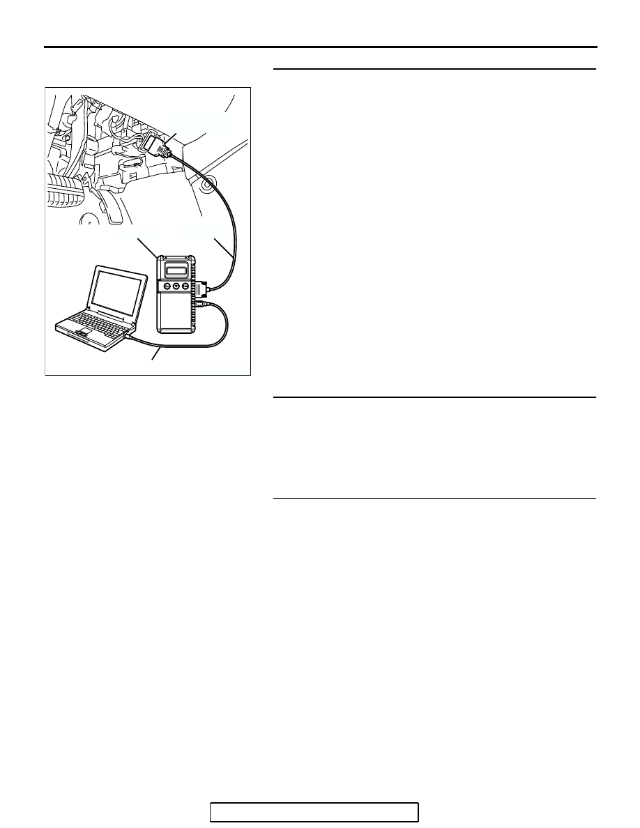
STEP 4. Using scan tool MB991958, check data list.
(1) Turn the ignition switch to the "ON" position.
(2) Check the following items of the data list. Refer to Data List 

Reference Tabl

P.13A-1083

.

a. Item 39: Cylinder 1, 4 Heated Oxygen Sensor (front).
b. Item 11: Cylinder 2, 3 Heated Oxygen Sensor (front).

• Voltage should fluctuate between 0 − 0.4 volt and 0.6 − 

1.0 volt while idling after the engine has been warmed.

(3) Turn the ignition switch to the "LOCK" (OFF) position.
Q: Are they operating properly?

YES : Replace the heated oxygen sensor (front). Then 

confirm that the malfunction symptom is eliminated. If 
not resolved, go to step 6.

NO :  Go to Step 5.

STEP 5. Check the fuel pressure.
Refer to On-vehicle Service 

− Fuel Pressure Test 

P.13A-1124

.

Q: Is the fuel pressure normal?

YES : Go to Step 6.
NO :  Repair or replace it. Then confirm that the malfunction 

symptom is eliminated.

STEP 6. Check the following items.
(1) Check the following items, and repair or replace the 

defective items.

a. Check the injectors for fuel leakage.
b. Check the ignition coil and spark plugs.

c. Check compression pressure.

d. Check the positive crank case ventilation system.
e. Check the evaporative emission system.

f. Check the EGR system.

(2) Then check the malfunction symptom.
Q: Is the malfunction symptom eliminated?

YES : The check is completed.
NO :  Replace the catalytic converter. Then confirm that the 

malfunction symptom is eliminated. 

AK303804AB

MB991910

DATA LINK
CONNECTOR

MB991824

MB991827

MULTIPORT FUEL INJECTION (MFI) DIAGNOSIS

TSB Revision

MULTIPORT FUEL INJECTION (MFI) <2.4L ENGINE>

13A-1027

INSPECTION PROCEDURE 23: Transient, Mass Emission Tailpipe Test Failure.

.

COMMENT

• The test is failed when the air/fuel ratio is not con-

trolled to the ideal air/fuel ratio. This occurs due 
to the feedback control by heated oxygen sensor 
signals, insufficient EGR flow rate, or deteriorated 
catalyst.

NOTE: If the three-way catalyst temperature is low 
when checking the exhaust gas, the three-way cata-
lyst cannot sufficiently clean the emissions. Warm up 
the engine sufficiently before checking the exhaust, 
and check immediately.

.

TROUBLESHOOTING HINTS (The most 
likely causes for this case:)

• Malfunction of air/fuel ratio control system.

• Malfunction of the EGR system.

• Deteriorated catalyst.

DIAGNOSIS

Required Special Tools:

• MB991958: Scan Tool (MUT-III Sub Assembly)

• MB991824: V.C.I.

• MB991827: USB Cable

• MB991910: Main Harness A

STEP 1. Check the exhaust gas with the engine at normal 
operating temperature.
Q: Was the exhaust gas checked with engine warmed 

sufficiently?
YES : 
Go to Step 2.
NO :  Check it again after enough warm up.

STEP 2. Check the following items.
(1) Check the following items.

a. Check all vacuum hoses and connectors.
b. Check electrical wires and connectors for obvious prob-

lems.

c. Check the exhaust system for missing or damaged 

parts.

Q: Are they normal?

YES : Go to Step 3.
NO :  Repair or replace it. Then confirm that the malfunction 

symptom is eliminated.

STEP 3. Check the driveability.
Q: Is the driveability normal?

YES : Go to Step 4.
NO :  Refer to Trouble Symptom Chart 

P.13A-38

.

MULTIPORT FUEL INJECTION (MFI) DIAGNOSIS

TSB Revision

MULTIPORT FUEL INJECTION (MFI) <2.4L ENGINE>

13A-1028

STEP 4. Using scan tool MB991958, read the diagnostic 
trouble code (DTC).

CAUTION

To prevent damage to scan tool MB991958, always turn the 
ignition switch to the "LOCK" (OFF) position before con-
necting or disconnecting scan tool MB991958.
(1) Connect scan tool MB991958 to the data link connector.
(2) Turn the ignition switch to the "ON" position.
(3) Read the DTC.
(4) Turn the ignition switch to the "LOCK" (OFF) position.
Q: Is the DTC set?

YES : Refer to Diagnostic Trouble Code Chart 

P.13A-33

.

NO :  Go to Step 5.

STEP 5. Check the ignition timing.
Refer to GROUP 11A, On-vehicle Service 

− Ignition Timing 

Check 

P.11A-12

.

Q: Is the ignition timing normal?

YES : Go to Step 6.
NO :  Check that the crankshaft position sensor and timing 

belt cover are in the correct position. Then confirm 
that the malfunction symptom is eliminated. 

AK303804AB

MB991910

DATA LINK
CONNECTOR

MB991824

MB991827

MULTIPORT FUEL INJECTION (MFI) DIAGNOSIS

TSB Revision

MULTIPORT FUEL INJECTION (MFI) <2.4L ENGINE>

13A-1029

STEP 6. Using scan tool MB991958, check data list.

CAUTION

To prevent damage to scan tool MB991958, always turn the 
ignition switch to the "LOCK" (OFF) position before con-
necting or disconnecting scan tool MB991958.
(1) Connect scan tool MB991958 to the data link connector.
(2) Turn the ignition switch to the "ON" position.
(3) Check the following items in the data list. Refer to Data List 

Reference Tabl

P.13A-1083

.

a. Item 21: Engine Coolant Temperature Sensor.
b. Item 13: Intake Air Temperature Sensor.

c. Item 25: Barometric Pressure Sensor.

d. Item 69: Cylinder 1, 4 Heated Oxygen Sensor (rear).
e. Item 59: Cylinder 2, 3 Heated Oxygen Sensor (rear).

(4) Turn the ignition switch to the "LOCK" (OFF) position.
Q: Are they operating properly?

YES : Go to Step 7.
NO :  Repair or replace it. Then confirm that the malfunction 

symptom is eliminated.

STEP 7. Using scan tool MB991958, check data list item 39: 
Cylinder 1, 4 Heated oxygen sensor (front).
(1) Start the engine and run at idle.
(2) Set scan tool MB991958 to the data reading mode for item 

39, Cylinder 1, 4 Heated Oxygen Sensor (front).

• Warm up the engine. When the engine is decelerated 

suddenly from 4,000 r/min, the output voltage should 
increase from 0.2 volt or less to 0.6 

− 1.0 volt in a few 

seconds.

(3) Turn the ignition switch to the "LOCK" (OFF) position.
Q: Is the sensor operating properly?

YES : Go to Step 8.
NO :  Refer to DTC P0130 

− Cylinder 1, 4 Heated Oxygen 

Sensor Circuit (sensor 1) 

P.13A-192

, DTC P0131 

− 

Cylinder 1, 4 Heated Oxygen Sensor Low Voltage 
(sensor 1) 

P.13A-210

, DTC P0132 

− Cylinder 1, 4 

Heated Oxygen Sensor Circuit High Voltage (sensor 
1) 

P.13A-217

, DTC P0133 

− Cylinder 1, 4 Heated 

Oxygen Sensor Circuit Slow Response (sensor 1) 

P.13A-222

, DTC P0134 

− Cylinder 1, 4 Heated 

Oxygen Sensor Circuit No Activity Detected (sensor 
1) 

P.13A-228

.

AK303804AB

MB991910

DATA LINK
CONNECTOR

MB991824

MB991827

AK303804AB

MB991910

DATA LINK
CONNECTOR

MB991824

MB991827


Content   ..  894  895  896  897   ..