Mitsubishi Galant 9G. Manual - part 835


  Index      Mitsubishi     Mitsubishi Galant 9G - service repair manual


Search            


Content   ..  833  834  835  836   ..


Mitsubishi Galant 9G. Manual - part 835


MULTIPORT FUEL INJECTION (MFI) DIAGNOSIS

TSB Revision

MULTIPORT FUEL INJECTION (MFI) <2.4L ENGINE>

13A-782

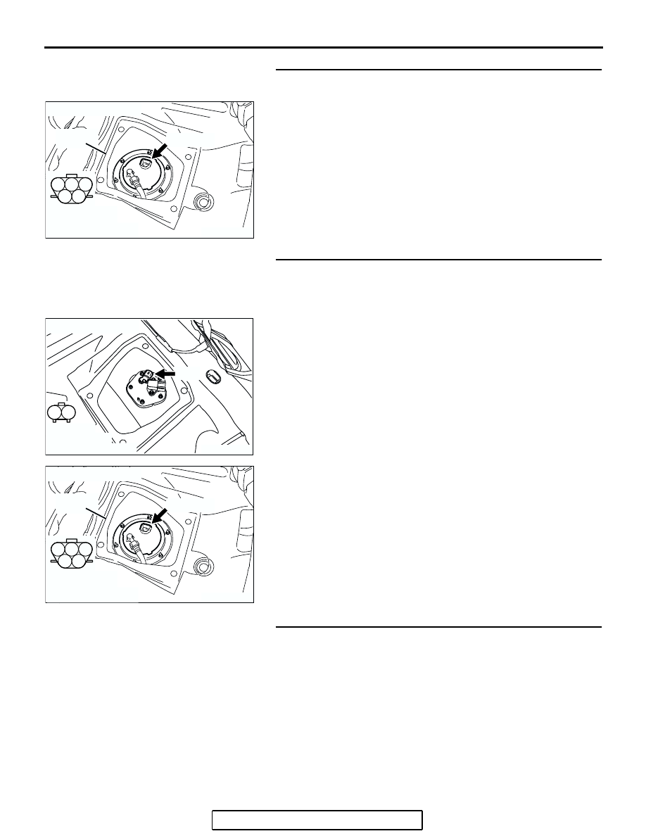
STEP 4. Check harness connector D-18 at fuel level sensor 
(main) for damage. 
Q: Is the harness connector in good condition?

YES : Go to Step 5.
NO :  Repair or replace them. Refer to GROUP 00E, 

Harness Connector Inspection 

P.00E-2

 Then go to 

Step 7.

STEP 5. Check for open circuit and short circuit to ground 
between fuel level sensor (main) connector D-18 (terminal 
No. 2) and fuel level sensor (sub) connector D-17 (terminal 
No. 1).
Q: Is the harness wire in good condition?

YES : Go to Step 6.
NO :  Repair it. Then go to Step 7.

STEP 6. Check the trouble symptoms.
(1) Carry out a test drive with the drive cycle pattern. Refer to 

Diagnostic Function 

− OBD-II Drive Cycle − Procedure 6 − 

Other Monitor 

P.13A-6

.

(2) Check the diagnostic trouble code (DTC).
Q: Is DTC P0463 set?

YES : Replace the PCM. Then go to Step 7.
NO :  It can be assumed that this malfunction is intermittent. 

Refer to GROUP 00, How to Use 
Troubleshooting/Inspection Service Points 

− How to 

Cope with Intermittent Malfunctions 

P.00-14

.

AK303840

1

2

3

4

5

SERVICE
HOLE

AB

CONNECTOR: D-18

D-18 (GR)

HARNESS 
CONNECTOR: 
COMPONENT SIDE

AK303878

1

2

AB

CONNECTOR: D-17

D-17

HARNESS 
CONNECTOR:
COMPONENT SIDE

AK303840

1

2

3

4

5

SERVICE
HOLE

AB

CONNECTOR: D-18

D-18 (GR)

HARNESS 
CONNECTOR: 
COMPONENT SIDE

MULTIPORT FUEL INJECTION (MFI) DIAGNOSIS

TSB Revision

MULTIPORT FUEL INJECTION (MFI) <2.4L ENGINE>

13A-783

STEP 7. Test the OBD-II drive cycle.
(1) Carry out a test drive with the drive cycle pattern. Refer to 

Diagnostic Function 

− OBD-II Drive Cycle − Procedure 6 − 

Other Monitor 

P.13A-6

.

(2) Check the diagnostic trouble code (DTC).
Q: Is DTC P0463 set?

YES : Retry the troubleshooting.
NO :  The inspection is complete.

DTC P0506: Idle Control Sytem RPM Lower Than Expected

CAUTION

If DTC P0506 has been set, TCL related DTC 
U1120 is also set. After P0506 has been diag-
nosed, don't forget to erase DTC U1120.

.

TECHNICAL DESCRIPTION

• The amount of air taken in during idling is regu-

lated by the opening and closing of the throttle 
valve.

• The PCM checks the difference between the 

actual engine speed and the target engine speed.

.

DESCRIPTIONS OF MONITOR METHODS

Difference between actual and target idle speed is 

over the specified value.

.

MONITOR EXECUTION

Continuous

.

MONITOR EXECUTION CONDITIONS 
(Other monitor and Sensor)

Other Monitor (There is no temporary DTC stored 

in memory for the item monitored below)

• Misfire monitor

• Exhaust gas recirculation (EGR) system monitor

• Fuel system monitor

Sensor (The sensor below is determined to be 

normal)

• Mass airflow sensor

• Engine coolant temperature sensor

• Intake air temperature sensor

• Barometric pressure sensor

• Throttle position sensor

.

MULTIPORT FUEL INJECTION (MFI) DIAGNOSIS

TSB Revision

MULTIPORT FUEL INJECTION (MFI) <2.4L ENGINE>

13A-784

DTC SET CONDITIONS
Logic Flow Chart

.

Check Conditions

• Under the closed loop idle speed control.

• The engine coolant temperature is more than 

77

°C (171°F).

• Battery positive voltage is higher than 10 volts.

• Power steering pressure switch: OFF

• Volumetric efficiency is lower than 40 percent.

• Barometric pressure is higher than 76 kPa (22.4 

in.Hg).

• Intake air temperature is higher than −10°C 

(14

°F).

• 25 seconds have elapsed from the start of the 

previous monitoring.

• Target throttle actuator control motor position is 

more than 255 steps.

Judgment Criteria

• The actual idle speed is more than 100 r/min 

lower than the target idle speed for 12 seconds.

.

OBD-II DRIVE CYCLE PATTERN

Refer to Diagnostic Function 

− OBD-II Drive Cycle − 

Procedure 6 

− Other Monitor 

P.13A-6

.

.

TROUBLESHOOTING HINTS (The most 
likely causes for this code to be set are:)

• Throttle valve area is dirty.

• PCM failed.

END

NO

NO

NO

YES

YES

YES

MALFUNCTION

GOOD

START

CALCULATE      Ne

MONITORING

CONDITIONS

   Ne = (ACTUAL-Ne) – (TARGET-Ne)
Ne: ENGINE SPEED

    Ne < –100 r/min OR

> 200 r/min

HAVE 12secs PASSED?

AK302165

MULTIPORT FUEL INJECTION (MFI) DIAGNOSIS

TSB Revision

MULTIPORT FUEL INJECTION (MFI) <2.4L ENGINE>

13A-785

DIAGNOSIS

Required Special Tools

• MB991958: Scan tool (MUT-III Sub Assembly)

• MB991824: V.C.I.

• MB991827: USB Cable

• MB991910: Main Harness A

STEP 1. Using scan tool MB991958, read the diagnostic 
trouble code (DTC).

CAUTION

To prevent damage to scan tool MB991958, always turn the 
ignition switch to the "LOCK" (OFF) position before con-
necting or disconnecting scan tool MB991958.
(1) Connect scan tool MB991958 to the data link connector.
(2) Turn the ignition switch to the "ON" position.
(3) Set scan tool MB991958, read the DTC.
(4) Turn the ignition switch to the "LOCK" (OFF) position.
Q: Is the diagnostic trouble code other than P0506 set?

YES : Refer to Diagnostic Trouble Code Chart 

P.13A-33

.

NO :  Go to Step 2.

STEP 2. Check the throttle body. (throttle valve area)
Q: Is the throttle valve area dirty?

YES : Perform cleaning. Refer to Throttle body (throttle 

valve area) cleaning 

P.13A-1124

. Then go to Step 4.

NO :  Go to Step 3.

STEP 3. Replace the throttle body assembly.
(1) Replace the throttle body assembly
(2) Turn the ignition switch to the "ON" position.
(3) After the DTC has been deleted, read the DTC again.
(4) Turn the ignition switch to the "LOCK" (OFF) position.
Q: Is DTC P0506 set?

YES : Replace the PCM. Then go to Step 4.
NO :  The inspection is complete.

AK303804AB

MB991910

DATA LINK
CONNECTOR

MB991824

MB991827


Content   ..  833  834  835  836   ..