Mitsubishi Galant 9G. Manual - part 822


  Index      Mitsubishi     Mitsubishi Galant 9G - service repair manual


Search            


Content   ..  820  821  822  823   ..


Mitsubishi Galant 9G. Manual - part 822


MULTIPORT FUEL INJECTION (MFI) DIAGNOSIS

TSB Revision

MULTIPORT FUEL INJECTION (MFI) <2.4L ENGINE>

13A-730

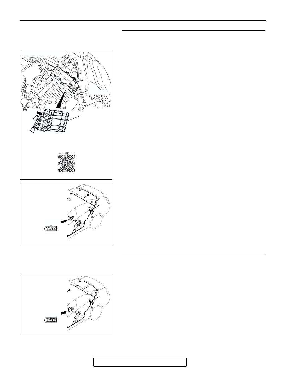
STEP 14. Check the harness wires between PCM 
connector B-20 terminal 22 and fuel tank differential 
pressure sensor connector D-23 terminal 2 for damage.
Q: Are the harness wires in good condition?

YES : Go to Step 17.
NO :  Repair the damaged harness wires. Then go to Step 

17.

STEP 15. Check fuel tank differential pressure sensor 
connector D-23 for loose, corroded or damaged terminals, 
or terminals pushed back in the connector.
Q: Is the connectors and terminals in good condition?

YES : Replace the fuel tank differential pressure sensor. 

Then go to Step 17.

NO :  Repair or replace the faulty components (Refer to 

GROUP 00E, Harness Connector Inspection 

P.00E-2

). Then go to Step 17.

AC306248

B-20 HARNESS

CONNECTOR:

COMPONENT SIDE

AB

B-20

CONNECTOR: B-20

PCM

AIR
CLEANER

AC305266

CONNECTOR: D-23

AB

D-23 (B)

AC305266

CONNECTOR: D-23

AB

D-23 (B)

MULTIPORT FUEL INJECTION (MFI) DIAGNOSIS

TSB Revision

MULTIPORT FUEL INJECTION (MFI) <2.4L ENGINE>

13A-731

STEP 16. Using scan tool MB991958, check data list item 
73: Fuel Tank Differential Pressure Sensor.

CAUTION

To prevent damage to scan tool MB991958, always turn the 
ignition switch to the "LOCK" (OFF) position before con-
necting or disconnecting scan tool MB991958.
(1) Connect scan tool MB991958 to the data link connector.

(2) Disconnect hose I from the evaporative emission canister, 

and plug the hose.

(3) Turn the ignition switch to the "ON" position.
(4) Remove the fuel cap.
(5) Set scan tool MB991958 to the data reading mode.

• Item 73, Fuel Tank Differential Pressure Sensor.

• The fuel tank pressure reading on the scan tool 

should be 

−1.5 to 1.5 kPa (−0.443 to 0.443 inHg).

(6) Connect the evaporative emission system pressure pump 

(Miller number 6872A) to the fuel tank filler tube by using 
fuel tank adapter (MLR-8382) and pressurize the fuel tank.

• The fuel tank pressure reading should increase.

(7) Turn the ignition switch to the "LOCK" (OFF) position. Then 

disconnect scan tool MB991958.

(8) Remove  the evaporative emission system pressure pump 

(Miller number 6872A) and the fuel tank adapter 
(MLR-8382), and reinstall the fuel cap.

(9) Connect hose I to the evaporative emission canister.

AC305412

AB

MB991910

DATA LINK

CONNECTOR

MB991824

MB991827

AC306778

AB

HOSE I

PLUG

AC306661

MULTIPORT FUEL INJECTION (MFI) DIAGNOSIS

TSB Revision

MULTIPORT FUEL INJECTION (MFI) <2.4L ENGINE>

13A-732

Q: Is the fuel tank pressure between 

1.5 and 1.5 kPa 

(

0.443 and 0.443 inHg)?

YES : It can be assumed that this malfunction is intermittent 

(Refer to GROUP 00, How to Use 
Troubleshooting/Inspection Service Points 

− How to 

Cope with Intermittent Malfunctions 

P.00-14

). Go to 

Step 17.

NO :  Replace the PCM (Refer to 

P.13A-1140

). Then go to 

Step 17     .

STEP 17. Perform the OBD-II drive cycle.
(1) Carry out a test drive with the drive cycle pattern (Refer to 

Diagnostic Function 

− OBD-ll Drive Cycle − Procedure 1 − 

Evaporative Emission System Leak Monitor 

P.13A-6

).

(2) Read the diagnostic trouble code (DTC).
Q: Is DTC P0453 set?

YES : Repeat the troubleshooting from Step 2.
NO :  The procedure is complete.

DTC P0455: Evaporative Emission System Leak Detected (Gross Leak)

AC306277

A

B

C

D

E

F

G

H

P

Q

R

O

N

M

I

J

K

L

AB

INTAKE MANIFOLD

FUEL TANK

EVAPORATIVE EMISSION
VENTILATION SOLENOID

CHECK VALVE

EVAPORATIVE EMISSION
PURGE SOLENOID

EVAPORATIVE 
EMISSION CANISTER

ONBOARD REFUELING
VAPOR RECOVERY(ORVR)
VENT VALVE MODULE

SYSTEM DIAGRAM

CHAMBER

MULTIPORT FUEL INJECTION (MFI) DIAGNOSIS

TSB Revision

MULTIPORT FUEL INJECTION (MFI) <2.4L ENGINE>

13A-733

.

TECHNICAL DESCRIPTION

• The fuel tank may be under a slight pressure or 

vacuum depending on the state of the Evapora-
tive Emission (EVAP) System. The PCM monitors 
and responds to these pressure/vacuum 
changes. If the pressure/vacuum varies from the 
specified range, the PCM will set DTC P0455.

• The PCM energizes the evaporative emission 

ventilation solenoid to shut off the evaporative 
emission canister outlet port.

• The evaporative emission purge solenoid is acti-

vated to apply engine manifold vacuum to the 
EVAP system.

• When the fuel system develops a vacuum of 2 

kPa (0.29 psi), the evaporative emission purge 
solenoid is turned "off" and the fuel system vac-
uum is maintained at 2 kPa (0.29 psi).

• The PCM determines whether there is a leak or 

clog in the fuel system by measuring the change 
in vacuum inside the fuel tank.

• The test is stopped when fuel vapor pressure is 

determined to be too high.

.

DESCRIPTIONS OF MONITOR METHODS

• Depressurizing EVAP system by intake manifold 

negative pressure is impossible within specified 
period.

.

MONITOR EXECUTION

• Once per driving cycle.

.

MONITOR EXECUTION CONDITIONS 
(OTHER MONITOR AND SENSOR)

Other Monitor (There is no temporary DTC stored 

in memory for the item monitored below)

• Evaporative emission purge solenoid monitor

• Evaporative emission purge system monitor

• Fuel tank differential pressure sensor monitor

• Evaporative emission ventilation solenoid monitor

• Fuel level sensor monitor

• Fuel temperature sensor monitor

 Sensor (The sensors below are determined to be 

normal)

• Mass airflow sensor

• Barometric pressure sensor

• Intake air temperature sensor

• Engine coolant temperature sensor

.

AC306400

AB

EVAPORATIVE EMISSION CANISTER

AC305066AC

EVAPORATIVE EMISSION
PURGE SOLENOID 

INTAKE
MANIFOLD

AC305053AC

EVAPORATIVE EMISSION
VENTILATION SOLENOID 


Content   ..  820  821  822  823   ..