Mitsubishi Galant 9G. Manual - part 812
MULTIPORT FUEL INJECTION (MFI) DIAGNOSIS
TSB Revision
MULTIPORT FUEL INJECTION (MFI) <2.4L ENGINE>
13A-690
(9) Connect hose I to the evaporative emission canister.
Q: Is the fuel tank pressure between
−1.5 and 1.5 kPa
(
−0.443 and 0.443 inHg)?
YES : It can be assumed that this malfunction is intermittent
(Refer to GROUP 00, How to Use
Troubleshooting/Inspection Service Points
− How to
Cope with Intermittent Malfunctions
). Go to
Step 17.
NO : Replace the PCM (Refer to
). Then go to
Step 17 .
STEP 17. Perform the OBD-II drive cycle.
(1) Carry out a test drive with the drive cycle pattern (Refer to
Diagnostic Function
− OBD-ll Drive Cycle − Procedure 1 −
Evaporative Emission System Leak Monitor
(2) Read the diagnostic trouble code (DTC).
Q: Is DTC P0451 set?
YES : Repeat the troubleshooting from Step 2.
NO : The procedure is complete.
DTC P0452: Evaporative Emission System Pressure Sensor Low Input
AC306277
A
B
C
D
E
F
G
H
P
Q
R
O
N
M
I
J
K
L
AC
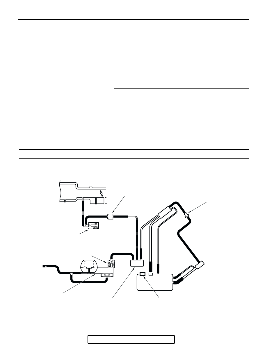
INTAKE MANIFOLD
FUEL TANK
EVAPORATIVE EMISSION
VENTILATION SOLENOID
CHECK VALVE
EVAPORATIVE EMISSION
PURGE SOLENOID
EVAPORATIVE
EMISSION CANISTER
ONBOARD REFUELING
VAPOR RECOVERY(ORVR)
VENT VALVE MODULE
FUEL TANK DIFFERENTIAL
PRESSURE SENSOR
SYSTEM DIAGRAM
CHAMBER