Mitsubishi Galant 9G. Manual - part 803


  Index      Mitsubishi     Mitsubishi Galant 9G - service repair manual


Search            


Content   ..  801  802  803  804   ..


Mitsubishi Galant 9G. Manual - part 803


MULTIPORT FUEL INJECTION (MFI) DIAGNOSIS

TSB Revision

MULTIPORT FUEL INJECTION (MFI) <2.4L ENGINE>

13A-654

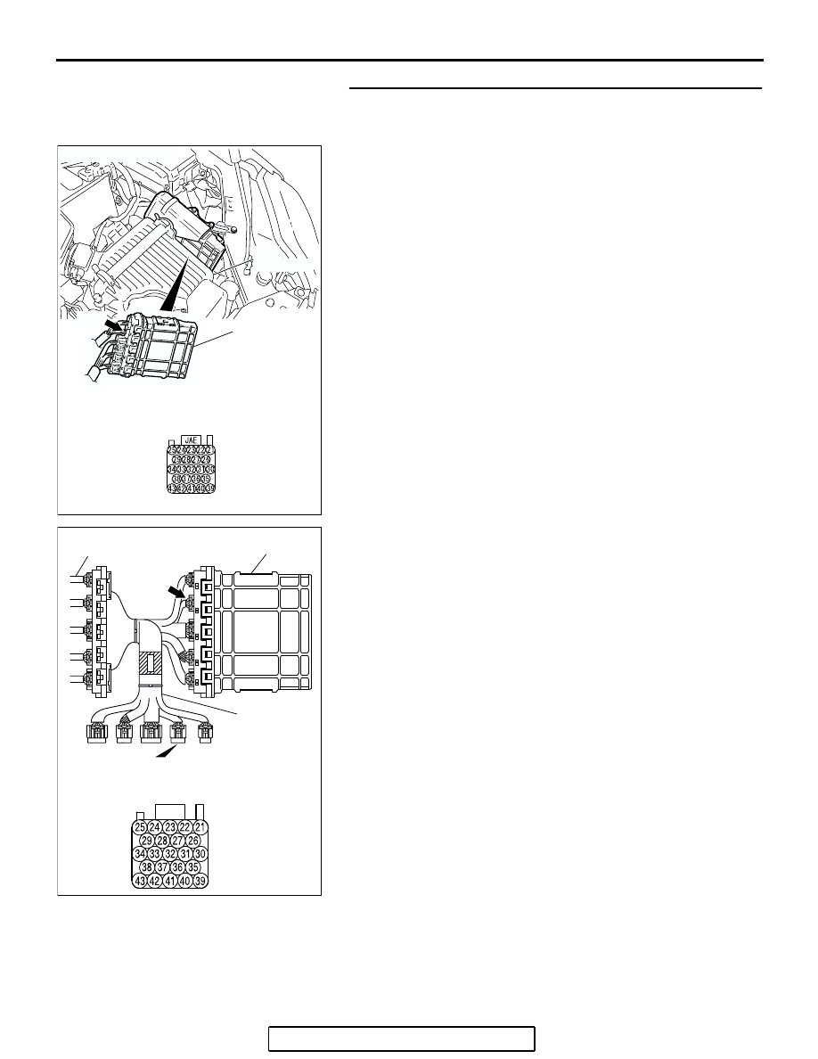
STEP 2. Measure the sensor output voltage at PCM 
connector B-20 by using check harness special tool 
MB991923. 
(1) Disconnect all the connectors from the PCM.

(2) Connect special tool MB991923 (check harness) between 

the PCM and the body-side harness connector.

(3) Turn the ignition switch to the "ON" position.
(4) Remove the fuel cap.

AC306248

B-20 HARNESS

CONNECTOR:

COMPONENT SIDE

AB

B-20

CONNECTOR: B-20

PCM

AIR
CLEANER

AC209793AJ

SPECIAL TOOL 23-PIN CONNECTOR
WITHOUT RED TAPE
(PCM CONNECTOR B-20)

B-20

PCM

MB991923

BODY SIDE
HARNESS

MULTIPORT FUEL INJECTION (MFI) DIAGNOSIS

TSB Revision

MULTIPORT FUEL INJECTION (MFI) <2.4L ENGINE>

13A-655

(5) Measure the voltage between terminal 23 and ground.

• The voltage should measure between 2.0 and 3.0 volts.

(6) Install the fuel cap.
(7) Turn the ignition switch to the "LOCK" (OFF) position.
Q: Is the measured voltage between 2.0 and 3.0 volts?

YES : Go to Step 16.
NO :  Go to Step 3.

STEP 3. Measure the 5-volt reference signal at PCM 
connector B-20 by using check harness special tool 
MB991923.
(1) Disconnect all the connectors from the PCM.

AC211194 AB

SPECIAL TOOL 23-PIN
CONNECTOR
(WITHOUT RED TAPE):
COMPONENT SIDE

AC306248

B-20 HARNESS

CONNECTOR:

COMPONENT SIDE

AB

B-20

CONNECTOR: B-20

PCM

AIR
CLEANER

MULTIPORT FUEL INJECTION (MFI) DIAGNOSIS

TSB Revision

MULTIPORT FUEL INJECTION (MFI) <2.4L ENGINE>

13A-656

(2) Connect special tool MB991923 (check harness) between 

the PCM and the body-side harness connector.

(3) Turn the ignition switch to the "ON" position.

(4) Measure the voltage between terminal 21 and ground.

• The voltage should measure between 4.9 and 5.1 volts.

(5) Turn the ignition switch to the "LOCK" (OFF) position.
Q: Is the measured voltage between 4.9 and 5.1 volts?

YES : Go to Step 5.
NO :  Go to Step 4.

AC209793AJ

SPECIAL TOOL 23-PIN CONNECTOR
WITHOUT RED TAPE
(PCM CONNECTOR B-20)

B-20

PCM

MB991923

BODY SIDE
HARNESS

AC211192AB

SPECIAL TOOL 23-PIN
CONNECTOR
(WITHOUT RED TAPE):
COMPONENT SIDE

MULTIPORT FUEL INJECTION (MFI) DIAGNOSIS

TSB Revision

MULTIPORT FUEL INJECTION (MFI) <2.4L ENGINE>

13A-657

STEP 4. Check PCM connector B-20 for loose, corroded or 
damaged terminals, or terminals pushed back in the 
connector.
Q: Are the connector and terminals in good condition?

YES : Go to Step 16.
NO :  Repair or replace the faulty components (Refer to 

GROUP 00E, Harness Connector Inspection 

P.00E-2

). Then go to Step 17.

AC306248

B-20 HARNESS

CONNECTOR:

COMPONENT SIDE

AB

B-20

CONNECTOR: B-20

PCM

AIR
CLEANER


Content   ..  801  802  803  804   ..