Mitsubishi Galant 9G. Manual - part 789
MULTIPORT FUEL INJECTION (MFI) DIAGNOSIS
TSB Revision
MULTIPORT FUEL INJECTION (MFI) <2.4L ENGINE>
13A-598
13A
DTC P0421: Warm Up Catalyst Efficiency Below Threshold (cylinder 1, 4)
.
TECHNICAL DESCRIPTION
• The signal from the rear heated oxygen sensor
differs from the front heated oxygen sensor. That
is because the catalytic converter purifies
exhaust gas. When the catalytic converter has
deteriorated, the signal from the front heated oxy-
gen sensor becomes similar to the rear heated
oxygen sensor.
• The PCM compares the output of the front and
rear heated oxygen sensor signals.
.
DESCRIPTIONS OF MONITOR METHODS
Front and rear heated oxygen sensor rich/lean
switching frequencies are nearly equal.
.
MONITOR EXECUTION
Continuous
.
MONITOR EXECUTION CONDITIONS
(Other monitor and Sensor)
Other Monitor (There is no temporary DTC stored
in memory for the item monitored below)
• Heated oxygen sensor (front) monitor
• Heated oxygen sensor (rear) monitor
• Heated oxygen sensor heater (front) monitor
• Heated oxygen sensor heater (rear) monitor
• Misfire monitor
• Fuel system monitor
• Air/fuel ratio feedback monitor
Sensor (The sensor below is determined to be
normal)
• Mass airflow sensor
• Engine coolant temperature sensor
• Intake air temperature sensor
• Barometric pressure sensor
• Throttle position sensor
• Accelerator pedal position sensor
.
DTC SET CONDITIONS
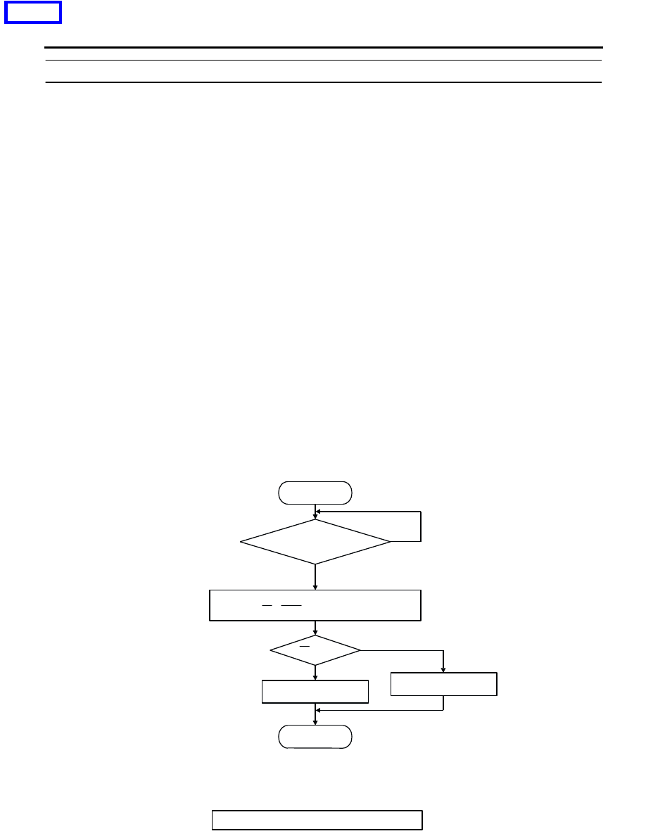
Logic Flow Chart
.
START
MONITORING
CONDITIONS
MALFUNCTION
GOOD
END
NO
NO
YES
YES
Rf > R0
CALCULATE AVERAGE FREQUENCY
RATIO (Rf = Fr/Ff) OF SPECIFIED TIMES
R0: AVERAGE THRESHOLD VALUE.
AK302038
<<PREVIOUS