Mitsubishi Galant 9G. Manual - part 756
MULTIPORT FUEL INJECTION (MFI) DIAGNOSIS
TSB Revision
MULTIPORT FUEL INJECTION (MFI) <2.4L ENGINE>
13A-466
DTC SET CONDITIONS <Circuit continuity
− open circuit and shorted low>
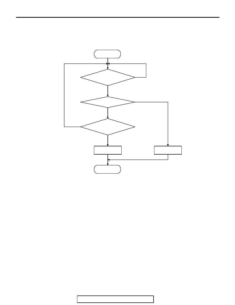
Logic Flow Chart
Check Conditions
• Engine is running.
Judgment Criteria
• The supply voltage is 3 volts or less without the
injector driving.
.
START
END
NO
NO
NO
YES
YES
YES
MALFUNCTION
GOOD
MONITORING
CONDITIONS
CONTINUOUS
FAILURE FOR 2secs
INJ. SURGE V
<= 3 V
AK401614