Mitsubishi Galant 9G. Manual - part 712


  Index      Mitsubishi     Mitsubishi Galant 9G - service repair manual


Search            


Content   ..  710  711  712  713   ..


Mitsubishi Galant 9G. Manual - part 712


MULTIPORT FUEL INJECTION (MFI) DIAGNOSIS

TSB Revision

MULTIPORT FUEL INJECTION (MFI) <2.4L ENGINE>

13A-290

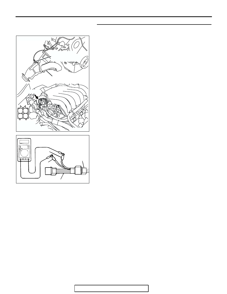
STEP 2. Check the cylinder 1, 4 heated oxygen sensor 
(rear).
(1) Disconnect cylinder 1, 4 heated oxygen sensor (rear) 

connector B-38 and connect test harness special tool, 
MD996484, to the connector on the cylinder 1, 4 heated 
oxygen (rear) sensor side.

(2) Measure the resistance between heated oxygen sensor 

connector terminal No. 1 (red clip) and terminal No. 3 (blue 
clip).

Standard value: 11 

 18 ohms [at 20°C (68°F)]

Q: Is the measured resistance between 11 and 18 ohms [at 

20

°C (68°F)]?

YES : Go to Step 3.
NO :  Replace the cylinder 1, 4 heated oxygen sensor 

(rear). Then go to Step 12.

AK203100

1

2

3

4

RIGHT BANK
HEATED OXYGEN
SENSOR (REAR)

RIGHT BANK
EXHAUST
MANIFOLD

AB

CONNECTOR: B-02

B-02 (GR)

HARNESS
CONNECTOR:
COMPONENT SIDE

AKX01624

HEATED
OXYGEN
SENSOR
COMPONENT
SIDE
CONNECTOR

MD998464

BLUE

RED

AU

MULTIPORT FUEL INJECTION (MFI) DIAGNOSIS

TSB Revision

MULTIPORT FUEL INJECTION (MFI) <2.4L ENGINE>

13A-291

STEP 3. Measure the power supply voltage at cylinder 1, 4 
heated oxygen sensor (rear) harness side connector B-38.
(1) Disconnect the connector B-38 and measure at the harness 

side.

(2) Turn the ignition switch to the "ON" position.

(3) Measure the voltage between terminal No. 1 and ground.

• Voltage should be battery positive voltage.

(4) Turn the ignition switch to the "LOCK" (OFF) position.
Q: Is battery positive voltage (approximately 12 volts) 

present?
YES : 
Go to Step 5.
NO :  Go to Step 4.

STEP 4. Check harness connector B-17X at the MFI relay 
for damage.
Q: Is the harness connector in good condition?

YES : Repair harness wire between MFI relay connector 

B-17X (terminal No. 4) and cylinder 1, 4 heated 
oxygen sensor (rear) connector B-38 (terminal No. 1) 
because of open circuit or short circuit to ground. 
Then go to Step 12.

NO :  Repair or replace it. Refer to GROUP 00E, Harness 

Connector Inspection 

P.00E-2

. Then go to Step 12. 

AK303826

1

2

3

4

AB

HARNESS 
CONNECTOR:
COMPONENT SIDE

CONNECTOR: B-38

B-38 (B)

CYLINDER 1, 4
HEATED OXYGEN
SENSOR (REAR)

AKX01498

B-38 HARNESS 
CONNECTOR: 
COMPONENT SIDE

1

2

3

4

BH

AK303806

2

1

3

4

AB

CONNECTOR: B-17X

B-17X

RELAY BOX
TRIANGLE 
MARK

HARNESS CONNECTOR:
COMPONENT SIDE

MULTIPORT FUEL INJECTION (MFI) DIAGNOSIS

TSB Revision

MULTIPORT FUEL INJECTION (MFI) <2.4L ENGINE>

13A-292

STEP 5. Measure the power supply voltage at PCM 
connector B-23 by using power plant ECU check harness 
special tool MB991923.
(1) Disconnect the all PCM connectors and connect power 

plant ECU check harness special tool MB991923 between 
the separated connectors.

(2) Turn the ignition switch to the "ON" position.

127 126 125 124 123 122 121

133 132 131 130 129 128

140 139 138 137 136 135 134

146 145 144 143 142 141

153 152 151 150 149 148 147

AK303058

HARNESS CONNECTOR: 
COMPONENT SIDE

CONNECTOR: B-23

B-23

PCM

AB

AIR CLEANER

AK202954

127 126 125 124 123 122 121

133 132 131 130 129 128

140 139 138 137 136 135 134

146 145 144 143 142 141

153 152 151 150 149 148 147

AB

POWER PLANT ECU 
CHECK HARNESS CONNECTOR

MB991923

PCM

MULTIPORT FUEL INJECTION (MFI) DIAGNOSIS

TSB Revision

MULTIPORT FUEL INJECTION (MFI) <2.4L ENGINE>

13A-293

(3) Measure the voltage between terminal No. 138 and ground.

• Voltage should be battery positive voltage.

(4) Turn the ignition switch to the "LOCK" (OFF) position.
Q: Is battery positive voltage (approximately 12 volts) 

present?
YES : 
Go to Step 8.
NO :  Go to Step 6.

STEP 6. Check harness connector B-23 at PCM for 
damage.
Q: Is the harness connector in good condition?

YES : Go to Step 7.
NO :  Repair or replace it. Refer to GROUP 00E, Harness 

Connector Inspection 

P.00E-2

. Then go to Step 12. 

127 126 125 124 123 122 121

133 132 131 130 129 128

140 139 138 137 136 135 134

146 145 144 143 142 141

153 152 151 150 149 148 147

AK203104 AB

POWER PLANT ECU 
CHECK HARNESS 
CONNECTOR 

127 126 125 124 123 122 121

133 132 131 130 129 128

140 139 138 137 136 135 134

146 145 144 143 142 141

153 152 151 150 149 148 147

AK303058

HARNESS CONNECTOR: 
COMPONENT SIDE

CONNECTOR: B-23

B-23

PCM

AB

AIR CLEANER


Content   ..  710  711  712  713   ..