Mitsubishi Galant 9G. Manual - part 687
MULTIPORT FUEL INJECTION (MFI) DIAGNOSIS
TSB Revision
MULTIPORT FUEL INJECTION (MFI) <2.4L ENGINE>
13A-190
DTC P0128: Coolant Thermostat (Coolant Temperature Below Thermostat Regulating Temperature)
.
TECHNICAL DESCRIPTION
• The PCM checks the time for the cooling water
temperature to reach the judgment temperature.
.
DESCRIPTIONS OF MONITOR METHODS
Engine coolant temperature does not reach 77
°C
(171
°F) within specified period after cold start.
.
MONITOR EXECUTION
Once per driving cycle
.
MONITOR EXECUTION CONDITIONS
(Other monitor and Sensor)
Other Monitor (There is no temporary DTC stored
in memory for the item monitored below)
• Not applicable
Sensor (The sensor below is determined to be
normal)
• Mass airflow sensor
• Engine coolant temperature sensor
• Intake air temperature sensor
.
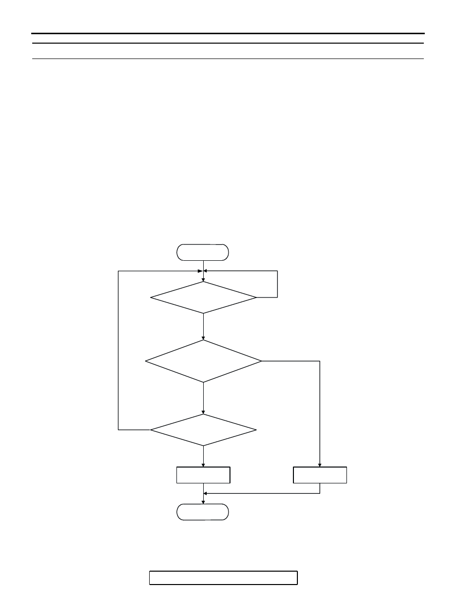
DTC SET CONDITIONS
Logic Flow Chart
.
START
END
YES
NO
NO
YES
MALFUNCTION
GOOD
TIME HAVE PASSED
AFTER STARTING?*
ENGINE COOLANT TEMP.
>=77˚C (171˚F)
*: See DTC SET CONDITIONS-JUDGMENT CRITERIA
MONITORING
CONDITIONS?
NO
YES
AK204044