Mitsubishi Galant 9G. Manual - part 605


  Index      Mitsubishi     Mitsubishi Galant 9G - service repair manual


Search            


Content   ..  603  604  605  606   ..


Mitsubishi Galant 9G. Manual - part 605


INTAKE MANIFOLD AND FUEL PARTS

TSB Revision

ENGINE OVERHAUL <3.8L ENGINE>

11D-18

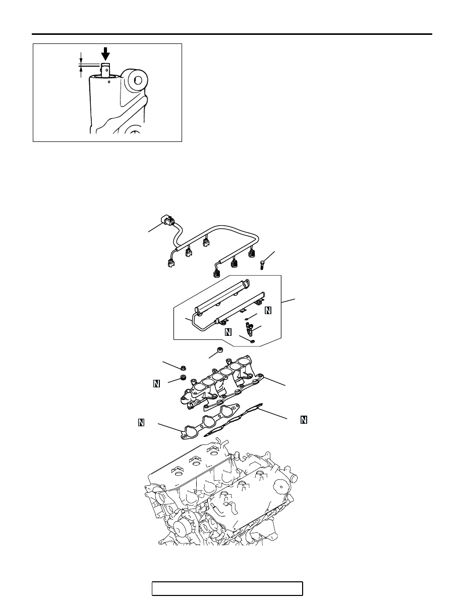
4. Press the rod with a force of 98 to 196 N (22 to 44 pounds) 

and measure the movement of the rod.
If the measured value is out of the standard value, replace 
the auto-tensioner.

Standard value: 1.0 mm (0.03 inch) or less

INTAKE MANIFOLD AND FUEL PARTS

REMOVAL AND INSTALLATION

M1113004300206

AK204324

MOVEMENT

98 TO 196 N
(22 TO 44 lb)

AB

AK203973

12 ± 1 N·m
107 ± 8 in-lb

20 – 23 N·m
15 – 17 ft-lb

2

1

8

3

10

10

6

5

4

9

7

AB

INTAKE MANIFOLD AND FUEL PARTS

TSB Revision

ENGINE OVERHAUL <3.8L ENGINE>

11D-19

INSTALLATION SERVICE POINTS

.

>>A<< INTAKE MANIFOLD INSTALLATION

1. Tighten the nuts "R" to 6.4 

± 1.5 N⋅m (57 ± 13 in-lb).

2. Tighten the nuts "L" to the specified torque.

Tightening torque: 20 

 23 Nm (15  17 ft-lb)

3. Tighten the nuts "R" to the specified torque.

Tightening torque: 20 

 23 Nm (15  17 ft-lb)

4. Tighten the nuts "L" to the specified torque.

Tightening torque: 20 

 23 Nm (15  17 ft-lb)

5. Tighten the nuts "R" to the specified torque.

Tightening torque: 20 

 23 Nm (15  17 ft-lb)

.

>>B<< INJECTOR INSTALLATION

CAUTION

Use care not to let engine oil enter the fuel rail.
1. Apply clean engine oil to the O-ring.
2. Insert the injector into the fuel rail.
3. Make sure the injector rotates smoothly. If not, remove the 

injector to check the O-ring for damage, and replace the 
O-ring if necessary. Then reinsert the injector and check that 
it rotates smoothly.

4. Confirm the protrusion of injector is at center. If not, rotate 

the injector for protrusion to be center.

REMOVAL STEPS

1. INJECTOR HARNESS
2. INJECTOR AND FUEL RAIL
3. INSULATOR
4. INSULATOR

>>B<<

5. INJECTOR

6. O-RING
7. FUEL RAIL
8. CONED DISC  SPRING

>>A<<

9. INTAKE MANIFOLD
10. INTAKE MANIFOLD GASKET

REMOVAL STEPS (Continued)

AKX00680

TIMING
BELT SIDE

NUT "R"

NUT "L"

AB

AK302905AB

FUEL RAIL

INJECTOR

AK302906AB

INJECTOR

FUEL RAIL

WATER PUMP & WATER HOSE

TSB Revision

ENGINE OVERHAUL <3.8L ENGINE>

11D-20

WATER PUMP & WATER HOSE

REMOVAL AND INSTALLATION

M1113017900286

AK302897AB

19 ± 1 N·m
14 ± 1 ft-lb

19 ± 1 N·m
14 ± 1 ft-lb

19 ± 1 N·m
14 ± 1 ft-lb

11 ± 1 N·m
95 ± 9 in-lb

29 ± 10 N·m
22 ± 7 ft-lb

42 ± 8 N·m
31 ± 6 ft-lb
(M10 BOLT)

24 ± 3 N·m
17 ± 2 ft-lb
(M8 BOLT)

4

5

2

6

3

1

9

12

11

8

7

7

10

REMOVAL STEPS

1. WATER HOSE
2. WATER HOSE

>>D<<

3. ENGINE COOLANT TEMPERATURE 

SENSOR

4. WATER INLET FITTING

>>C<<

5. THERMOSTAT
6. THERMOSTAT HOUSING

>>B<<

7. THERMOSTAT HOUSING GASKET

>>A<<

8. O-RING 

>>A<<

9. WATER INLET PIPE

>>A<<

10. O-RING
11. WATER PUMP
12. WATER PUMP  GASKET

REMOVAL STEPS (Continued)

WATER PUMP & WATER HOSE

TSB Revision

ENGINE OVERHAUL <3.8L ENGINE>

11D-21

INSTALLATION SERVICE POINTS

.

>>A<< O-RING AND WATER INLET PIPE INSTAL-
LATION

CAUTION

Keep the O-ring free of oil or grease.
1. Attach a new O-ring to each end of the water inlet pipe.
2. Wet the O-ring with water.
3. Insert the front end of the pipe into the water pump.

.

>>B<< THERMOSTAT HOUSING GASKET 
INSTALLATION

Install the thermostat housing gasket so that the tab is posi-
tioned as shown in the illustration.

.

>>C<< THERMOSTAT INSTALLATION

1. Check that the rubber ring is free from damage and seated 

correctly in the thermostat flange.

2. Install the thermostat as shown in the illustration. The jiggle 

valve must be at the top position.

.

AKX00711

O-RING

WATER INLET 
PIPE

AB

AK302907

TAB

AB

AKX00670AB

JIGGLE VALVE


Content   ..  603  604  605  606   ..