Mitsubishi Galant 9G. Manual - part 598


  Index      Mitsubishi     Mitsubishi Galant 9G - service repair manual


Search            


Content   ..  596  597  598  599   ..


Mitsubishi Galant 9G. Manual - part 598


CRANKSHAFT AND CYLINDER BLOCK

TSB Revision

ENGINE OVERHAUL <2.4L ENGINE>

11B-64

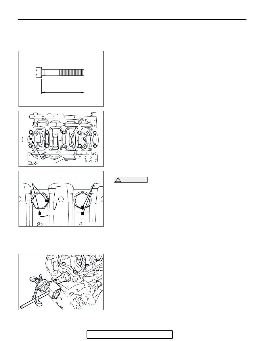
>>D<< BEARING CAP/BEARING CAP BOLT 
INSTALLATION

1. Install the bearing caps so that the arrow points to the timing 

belt side.

2. Before installing the bearing cap bolts, check that the shank 

length of each bolt meets the limit. If it exceeds the limit, 
replace the bolt.

Limit: 71.1 mm (2.79 inches)

3. Apply engine oil to the threaded portion and bearing surface 

of the bolt.

4. Tighten the bolts to the specified torque in the tightening 

sequence shown.

Tightening torque: 25 

± 2Nm (18 ± 1 ft-lb)

5. Make a paint mark on the head of each bolt.

CAUTION

• If the bolt is overtightened, loosen the bolt completely 

and then retighten it by repeating the tightening proce-
dure from step 4.

• If the bolt is turned less than 90 degrees, proper fasten-

ing performance may not be achieved. Be sure to turn 
the bolt exactly 90 degrees.

6. Make a paint mark on the bearing cap 90 degrees from the 

paint mark made on the bolt, in the direction of tightening the 
bolt.

7. Turn each bolt 90 degrees in the tightening sequence 

specified in step 4, and make sure that the paint marks on 
the bolt and cap are aligned.

8. Make sure that the crankshaft turns smoothly and the end 

play is correct. If the end play exceeds the limit, replace the 
number 3 crankshaft bearings.

Standard value: 0.05 

 0.25 mm (0.002  0.009 inch)

Limit: 0.40 mm (0.015 inch)

.

AK301471AC

SHANK LENGTH

AK300199

1

5

9

10

6

2

AC

8

4

3

7

ARROW

AK300200

PAINT MARK

AC

PAINT MARK

90˚

AK300201

CRANKSHAFT AND CYLINDER BLOCK

TSB Revision

ENGINE OVERHAUL <2.4L ENGINE>

11B-65

>>E<< OIL SEAL INSTALLATION

Using special tools MD998776 and MB990938, press-fit the oil 
seal in the case.

.

>>F<< SEALANT APPLICATION TO OIL SEAL 
CASE

1. Apply sealant MITSUBISHI Genuine Part number 

MD970389 or equivalent to the gasket surface of oil seal 
case.
NOTE: Be sure to install the case quickly while the sealant is 
wet (within 15 minutes).

2. Apply engine oil to the oil seal lip, and then install the oil seal 

case onto the cylinder block.
NOTE: After installation, keep the sealed area away from 
the oil for approximately one hour.

INSPECTION

M1113008800429

.

CRANKSHAFT JOURNAL OIL CLEARANCE 
<PLASTIC GAUGING MATERIAL METHOD>

1. Remove oil from the crankshaft journal and crankshaft 

bearing.

2. Install the crankshaft.
3. Cut the plastic gauging material to the same length as the 

width of bearing and place it on journal in parallel with its 
axis.

4. Install the crankshaft bearing cap carefully and tighten the 

bolts to the specified torque. 

5. Carefully remove the crankshaft bearing cap.

AK300202

MB990938

MD998776

AC

AK300576AB

AK300203

PLASTIC GAUGING MATERIAL

AC

CRANKSHAFT AND CYLINDER BLOCK

TSB Revision

ENGINE OVERHAUL <2.4L ENGINE>

11B-66

6. Measure the width of the plastic gauging material at its 

widest part by using a scale printed on the plastic gauging 
material package.

Standard value: 0.02 

 0.04 mm (0.0008  0.0015 inch)

Limit: 0.1 mm (0.003 inch)

.

CYLINDER BLOCK 

1. Visually check for scratches, rust, and corrosion. 

Use also a flaw detecting agent for the check. If defects are 
evident, correct or replace.

2. Using a straightedge and feeler gauge, check the block top 

surface for warpage. Make sure that the surface is free from 
gasket chips and other foreign matter.

Standard value: 0.05 mm (0.0020 inch)
Limit: 0.1 mm (0.003 inch)

3. If the distortion is excessive, correct within the allowable 

limit or replace.

Grinding limit: 0.2 mm (0.007 inch)
*Includes/combined with cylinder head grinding
Cylinder block height (when new):
290 mm (11.4 inches)

4. Check cylinder walls for scratches and seizure. If defects 

are evident, replace or bore to oversize and replace pistons 
and piston rings.

5. Using a cylinder gauge, measure the cylinder bore and 

cylindrically. If worn badly, correct the cylinder to an oversize 
and replace the piston and piston rings. Measure at the 
points shown in the illustration.

Standard value:

Cylinder inner diameter 87.0 mm (3.43 inches)
Cylindrically 0.01 mm (0.0003 inch) or less

.

AK300204

PLASTIC GAUGING MATERIAL

AC

AK300205

A

B

C

D

E

F

G

AK300206

12mm

(0.47 in)

AC

A

B

CENTER

BOTTOM

CRANKSHAFT AND CYLINDER BLOCK

TSB Revision

ENGINE OVERHAUL <2.4L ENGINE>

11B-67

BORING CYLINDER 

1. Oversize pistons to be used should be determined on the 

basis of the largest bore cylinder.

Piston size identification 

NOTE: Size mark is stamped on the piston top.

2. Measure the outside diameter (OD) of the piston to be used. 

Measure it in thrust direction as shown.

3. Based on the measured piston OD, calculate the boring 

finish dimension.

Boring  finish dimension = Piston OD +
(clearance between piston OD and cylinder) 

0.02 mm (0.0008 inch) (honing margin)

CAUTION

To prevent distortion that may result from temperature rise 
during honing, bore cylinders,  working from number  2 to 
number 4 to number 1 to number 3.
4. Bore all cylinders to the calculated boring finish dimension.
5. Hone to the final finish dimension (piston OD + clearance 

between piston OD and cylinder).

6. Check the clearance between the piston and cylinder.

Clearance between piston and cylinder:
0.02 

 0.04 mm (0.0008  0.0015 inch)

NOTE: When boring cylinders, finish all of four cylinders to 
the same oversize. Do not bore only one cylinder to an over-
size. 

SIZE

IDENTIFICATION MARK

0.50 mm (0.020 in) 
oversize diameter

50

AK300577AC

THRUST
DIRECTION

PISTON OUTSIDE
DIAMETER

AC


Content   ..  596  597  598  599   ..