Mitsubishi Galant 9G. Manual - part 565


  Index      Mitsubishi     Mitsubishi Galant 9G - service repair manual


Search            


Content   ..  563  564  565  566   ..


Mitsubishi Galant 9G. Manual - part 565


AUTOMATIC TRANSAXLE DIAGNOSIS

TSB Revision

AUTOMATIC TRANSAXLE

23A-338

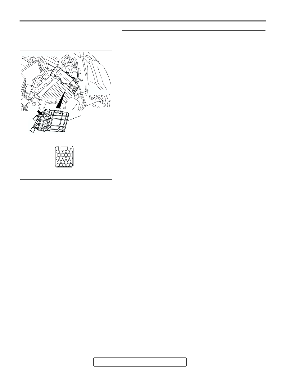
STEP 26. Check PCM connector B-20 for loose, corroded 
or damaged terminals, or terminals pushed back in the 
connector.
Q: Are the connector and terminals in good condition?

YES : Go to Step 4.
NO :  Repair or replace the damaged components. Refer to 

GROUP 00E, Harness Connector Inspection 

P.00E-2

.

AC306248AH

CONNECTOR: B-20

PCM

AIR
CLEANER

JAE

41

37

32

40

39

23

21 22

35

31

30

26

36

27

43

42

25

24

38

34

29

33

28

B-20

AUTOMATIC TRANSAXLE DIAGNOSIS

TSB Revision

AUTOMATIC TRANSAXLE

23A-339

INSPECTION PROCEDURE 16: Shift Position Indicator Light System <Vehicles with Sport Mode>

.

WITHOUT ELECTRONIC
BRAKE-FORCE
DISTRIBUTION (EBD)
AND ANTI-LOCK
BRAKING SYSTEM
(ABS)

WITHOUT ELECTRONIC
BRAKE-FORCE
DISTRIBUTION (EBD)
AND ANTI-LOCK
BRAKING SYSTEM
(ABS)

WITH ELECTRONIC
BRAKE-FORCE
DISTRIBUTION (EBD)
AND ANTI-LOCK
BRAKING SYSTEM
(ABS)

WITH ELECTRONIC
BRAKE-FORCE
DISTRIBUTION (EBD)
AND ANTI-LOCK
BRAKING SYSTEM
(ABS)

JOINT
CONNECTOR (4)

POWERTRAIN
CONTROL
MODULE

ABS-ECU

CPU

RHEOSTAT CIRCUIT

COMBINATION
METER

AC209763AC

Communication circuit (CAN Communcation Line) between PCM and Combination Meter

JOINT
CONNECTOR (3)

AUTOMATIC TRANSAXLE DIAGNOSIS

TSB Revision

AUTOMATIC TRANSAXLE

23A-340

CIRCUIT OPERATION

• The PCM detects the transmission range ("P," 

"R," "N," "D," sport mode "4," "3," "2," or "1"), and 
display it on the combination meter.

.

COMMENT

Connector(s), wiring harness in the CAN bus line 
between the PCM and the combination meter, power 
supply to the PCM, the combination meter, the PCM 
may be defective.

.

TROUBLESHOOTING HINTS (The most 
likely causes for this condition:)

• Malfunction of the combination meter

• Damaged harness, connector

• Malfunction of the PCM

DIAGNOSIS

Required Special Tool:

• MB991958: Scan Tool (MUT-III Sub Assembly)

• MB991824: V.C.I.

• MB991827: MUT-III USB Cable

• MB991910: MUT-III Main Harness A

STEP 1. Using scan tool MB991958, diagnose the CAN bus 
line.

CAUTION

To prevent damage to scan tool MB991958, always turn the 
ignition switch to the "LOCK" (OFF) position before con-
necting or disconnecting scan tool MB991958.
Use scan tool MB991958 to diagnose the CAN bus lines.
(1) Connect scan tool MB991958 to the data link connector.
(2) Turn the ignition switch to the "ON" position.
(3) Diagnose the CAN bus line.
(4) Turn the ignition switch to the "LOCK" (OFF) position.
Q: Is the check result properly?

YES : Go to Step 2.
NO :  Repair the CAN bus lines (Refer to GROUP 54C, 

Diagnosis-CAN Bus Diagnostic Chart 

P.54C-14

).

AC305412

AB

MB991910

DATA LINK

CONNECTOR

MB991824

MB991827

AUTOMATIC TRANSAXLE DIAGNOSIS

TSB Revision

AUTOMATIC TRANSAXLE

23A-341

STEP 2. Using scan tool MB991958, read the MFI 
diagnostic trouble code.
(1) Connect scan tool MB991958 to the data link connector.
(2) Turn the ignition switch to the "ON" position.
(3) Check for MFI diagnostic trouble code.
(4) Turn the ignition switch to the "LOCK" (OFF) position.
Q: Is DTC U1108 set?

YES : Refer to GROUP 13A <2.4L Engibe>, Diagnostic 

Trouble Code Procedures 

P.13A-958

 DTC U1108: 

Combination Meter-ECU CAN Communication Time 
Out or refer to GROUP 13B <3.8L Engibe>, 
Diagnostic Trouble Code Procedures 

P.13B-1003


DTC U1108: Combination Meter-ECU CAN 
Communication Time Out.

NO :  Replace the PCM.

AC305412

AB

MB991910

DATA LINK

CONNECTOR

MB991824

MB991827


Content   ..  563  564  565  566   ..