Mitsubishi Galant 9G. Manual - part 475
DRIVE SHAFT ASSEMBLY
TSB Revision
FRONT AXLE
26-20
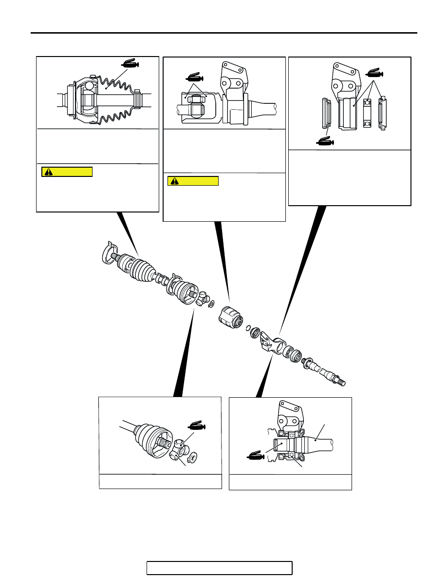
LUBRICATION POINTS
AC305985
GREASE: REPAIR KIT GREASE
AMOUNT USED: 120 ± 10 g
(4.2 ± 0.3 oz)<2.4L>, 165 ± 10 g
(5.8 ± 0.3 oz)<3.8L>
CAUTION
THE DRIVE SHAFT JOINT USES
SPECIAL GREASE. DO NOT MIX OLD
AND NEW OR DIFFERENT TYPES OF
GREASE.
GREASE: REPAIR KIT GREASE
AMOUNT USED: 140 ± 10 g
(4.9 ± 0.3 oz)<2.4L-LH>, 130 ± 10 g
(4.6 ± 0.3 oz)<2.4L-RH>, 220 ± 10 g
(7.8 ± 0.3 oz)<3.8L>
GREASE: REPAIR KIT GREASE
AMOUNT USED:
DUST SEAL INNER: 14 - 20 g
(0.5 - 0.7 oz)
DUST SEAL OUTER: 8 - 12 g
(0.3 - 0.4 oz)
THE DRIVE SHAFT JOINT USES
SPECIAL GREASE. DO NOT MIX OLD
AND NEW OR DIFFERENT TYPES OF
GREASE.
CAUTION
GREASE: REPAIR KIT GREASE
AB
14
GREASE: REPAIR KIT GREASE
10
5