Mitsubishi Galant 9G. Manual - part 461
AUTO-CRUISE CONTROL
TSB Revision
ENGINE AND EMISSION CONTROL
17-62
.
CIRCUIT OPERATION
The PCM detects "CRUISE" (MAIN) switch "ON" sig-
nal to illuminate the "CRUISE" indicator light on the
combination meter.
.
COMMENT
Connector(s), wiring harness in the CAN bus line
between the PCM and the combination meter, power
supply to the PCM, the combination meter, the PCM
may be defective.
.
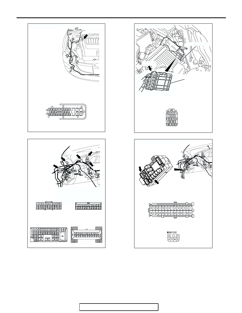
AC305209AB
A-02 (GR)
CONNECTOR: A-02
A-02 HARNESS CONNECTOR:
COMPONENT SIDE
AC305710
B-19 HARNESS
CONNECTOR:
COMPONENT SIDE
AC
B-19 (B)
CONNECTOR: B-19
AIR CLEANER
PCM
AC305232AO
CONNECTORS: C-01, C-02, C-03, C-29, C-101
C-29
C-01
C-101
C-03
C-02
C-01 AND C-03
HARNESS CONNECTOR:
COMPONENT SIDE
C-02 HARNESS
CONNECTOR:
COMPONENT SIDE
C-29 MALE SIDE
CONNECTOR
C-101 HARNESS
CONNECTOR:
COMPONENT SIDE
AC305720
C-215 HARNESS CONNECTOR:
COMPONENT SIDE
JUNCTION BLOCK
(FRONT VIEW)
AB
C-215
C-211
CONNECTORS: C-211, C-215
C-211 HARNESS CONNECTOR:
COMPONENT SIDE