Mitsubishi Galant 9G. Manual - part 438
TRACTION CONTROL SYSTEM (TCL) DIAGNOSIS
TSB Revision
TRACTION CONTROL SYSTEM (TCL)
13D-20
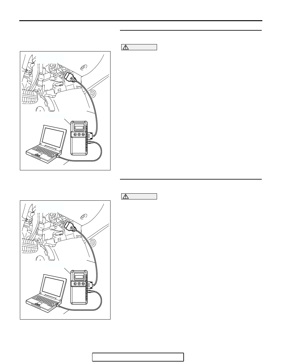
STEP 4. Using scan tool MB991958, read the diagnostic
trouble code.
CAUTION
To prevent damage to scan tool MB991958, always turn the
ignition switch to the "LOCK" (OFF) position before con-
necting or disconnecting scan tool MB991958.
(1) Connect scan tool MB991958 to the data link connector.
(2) Turn the ignition switch to the "ON" position.
(3) Use scan tool MB991958 to read the TCL diagnostic trouble
).
(4) Turn the ignition switch to the "LOCK" (OFF) position.
(5) Disconnect scan tool MB991958.
Q: Is DTC U1101 set?
YES : Replace the PCM. [Refer to GROUP 13B, Power
Control Module (PCM)
]. Then go to Step
NO : It can be assumed that this malfunction is intermittent.
(Refer to GROUP 00, How to Use
Troubleshooting/Inspection Service Points
− How to
Cope with Intermittent Malfunction
STEP 5. Using scan tool MB991958, read the diagnostic
trouble code.
CAUTION
To prevent damage to scan tool MB991958, always turn the
ignition switch to the "LOCK" (OFF) position before con-
necting or disconnecting scan tool MB991958.
(1) Connect scan tool MB991958 to the data link connector.
(2) Turn the ignition switch to the "ON" position.
(3) Use scan tool MB991958 to read the TCL diagnostic trouble
).
(4) Turn the ignition switch to the "LOCK" (OFF) position.
(5) Disconnect scan tool MB991958.
Q: Is DTC U1101 set?
YES : Replace the hydraulic unit (integrated with
ABS/TCL-ECU). (Refer to GROUP 35B
− Hydraulic
Unit
NO : It can be assumed that this malfunction is intermittent.
(Refer to GROUP 00, How to Use
Troubleshooting/Inspection Service Points
− How to
Cope with Intermittent Malfunction
AC305412
AB
MB991910
DATA LINK
CONNECTOR
MB991824
MB991827
AC305412
AB
MB991910
DATA LINK
CONNECTOR
MB991824
MB991827