Mitsubishi Galant 9G. Manual - part 372


  Index      Mitsubishi     Mitsubishi Galant 9G - service repair manual


Search            


Content   ..  370  371  372  373   ..


Mitsubishi Galant 9G. Manual - part 372


WINDSHIELD WIPER AND WASHER

TSB Revision

EXTERIOR

51-14

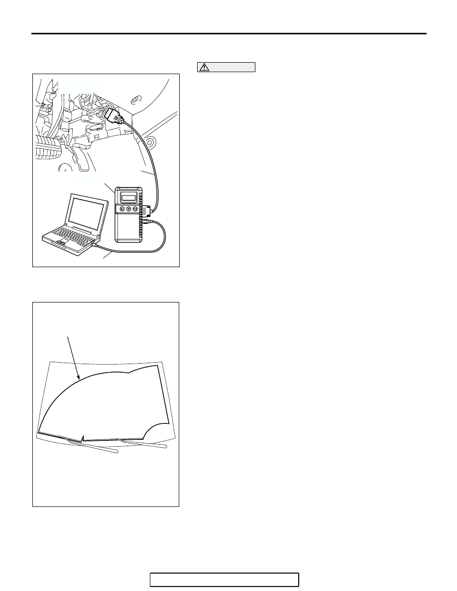
If the windshield intermittent wiper interval control is operated, 
the wiper interval should change.

CAUTION

To prevent damage to scan tool MB991958, always turn the 
ignition switch to the "LOCK" (OFF) position before con-
necting or disconnecting scan tool MB991958. 
1. Connect scan tool MB991958 to the data link connector.
2. Turn the ignition switch to the "ON" position.
3. Operate scan tool MB991958 according to the procedure 

below to display "Simulated Vehicle Speed Output."

(1) Select "SYSTEM SELECT."
(2) Select "SWS."
(3) Select "Simulated Vehicle Speed Output."

4. Holding the windshield intermittent wiper interval control, 

input the simulated vehicle speed with scan tool MB991958 
and check that the wiper interval changes as the vehicle 
speed changes.

5. If not, carry out the troubleshooting (Refer to GROUP 54B, 

SWS Diagnosis 

P.54B-59

).

WINDSHIELD WASHER FLUID EJECTION CHECK

M1511018400060

The windshield washer nozzle aiming cannot be adjusted. If the 
washer nozzles do not spray washer fluid within the windshield 
wiper wiping area, check the nozzles as follows:
1. Check that the windshield washer nozzles are fitted on the 

hood correctly, and reinstall them if necessary.

2. If the windshield washer nozzles are damaged, replace 

them (Refer to 

P.51-21

).

AC305412

AB

MB991910

DATA LINK

CONNECTOR

MB991824

MB991827

AC307151 AB

WINDSHIELD WIPER WIPING AREA

WINDSHIELD WIPER AND WASHER

TSB Revision

EXTERIOR

51-15

WINDSHIELD WIPER

REMOVAL AND INSTALLATION

M1511007900168

AC306698

AB

1

2

8

4.9 ± 0.5 N·m
43 ± 4 ft-lb

7.5 ± 1.4 N·m
66 ± 13 ft-lb

A

37 ± 3 N·m
18 ± 1 ft-lb

7

3

4

5

6

WINDSHIELD WIPER AND WASHER

TSB Revision

EXTERIOR

51-16

NOTE: For removal and installation of the wiper and 
washer switch, refer to GROUP 54A, Column switch 

P.54A-128

.

AC306703

SECTION B – B

SECTION C – C

5

5

6

CLIP

CLAW

VIEW A

NOTE

: CLIP POSITION

: CLAW POSITION

C

C

WINDSHIELD

SCREW

5

AB

B

B

WIPER BLADE REMOVAL STEPS

>>B<<

1. WIPER BLADE ASSEMBLY

>>B<<

2. WIPER BLADE RUBBER

>>A<<

3. WIPER ARM AND BLADE 

ASSEMBLY

WINDSHIELD WIPER MOTOR AND 
LINK  ASSEMBLY REMOVAL STEPS
4. FENDER HOLE COVER
5. FRONT DECK GARNISH 

ASSEMBLY

6. GUTTER
7. WINDSHIELD WIPER MOTOR AND 

LINK ASSEMBLY

8. FENDER COVER

WINDSHIELD WIPER MOTOR AND 
LINK ASSEMBLY REMOVAL STEPS 

WINDSHIELD WIPER AND WASHER

TSB Revision

EXTERIOR

51-17

INSTALLATION SERVICE POINTS

.

>>A<< WIPER ARM AND BLADE ASSEMBLY 
INSTALLATION

Install the wiper blade at the position specified above.

.

AC307178

AC306640

AC306641

AC

FENDER HOLE
COVER

FRONT DECK 
GARNISH

FRONT DECK GARNISH

WIPER BLADE (RH)

PLACE WIPER BLADE ON THE 
MARK OF WINDSHIELD

WIPER ARM AND 
BLADE ASSEMBLY (LH)

WINDSHIELD GLASS

WINDSHIELD GLASS

WIPER BLADE (LH)

SECTION D – D

SECTION E – E

D

D

38 ± 5 mm
(1.50 ± 0.20 inch)

38 ± 5 mm
(1.50 ± 0.20 inch)

FENDER HOLE
COVER

E

E

WIPER ARM AND 
BLADE ASSEMBLY (RH)


Content   ..  370  371  372  373   ..