Mitsubishi Galant 9G. Manual - part 347
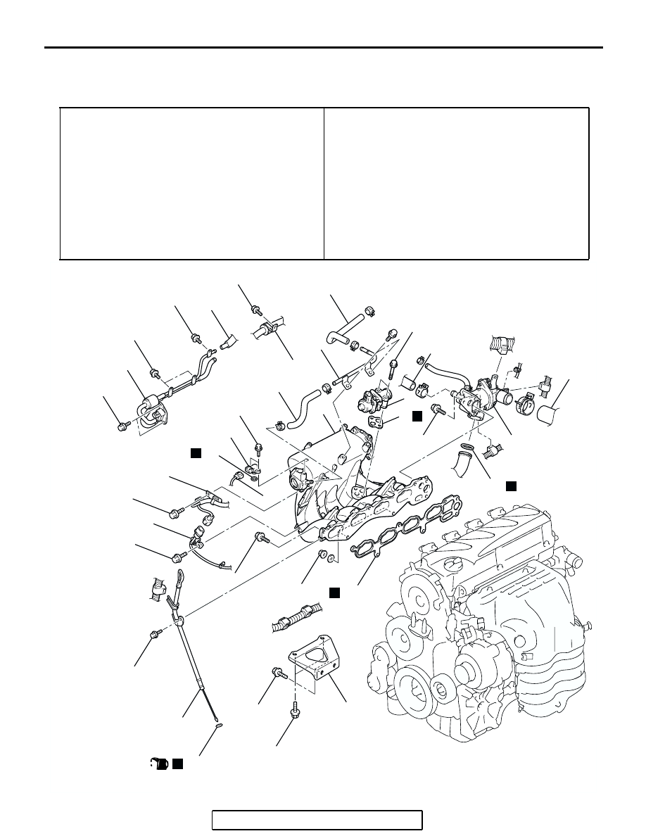
INTAKE MANIFOLD
TSB Revision
INTAKE AND EXHAUST
15-8
INTAKE MANIFOLD
REMOVAL AND INSTALLATION <2.4L ENGINE>
M1151003000813
Pre-removal Operation
• Fuel Line Pressure Reduction [Refer to GROUP 13A,
On-vehicle Service
− Fuel Pump Connector Disconnec-
tion (How to Reduce Pressurized Fuel Lines)
].
• Engine Coolant Draining (Refer to GROUP 14, On-vehicle
Service
• Air Cleaner Cover and Air Intake Hose Removal (Refer to
).
• Throttle Body Removal (Refer to GROUP 13A, Throttle
Body
• Delivery Pipe and Injector Assembly Removal (Refer to
GROUP 13A, Injector
Post-installation Operation
• Delivery Pipe and Injector Assembly Installation (Refer to
GROUP 13A, Injector
).
• Throttle Body Installation (Refer to GROUP 13A, Throttle
).
• Air Cleaner Cover and Air Intake Hose Installation (Refer
).
• Engine Coolant Refilling (Refer to GROUP 14, On-vehicle
Service
− Engine Coolant Replacement
AC306677
11 ± 1 N·m
98 ± 8 in-lb
11 ± 1 N·m
98 ± 8 in-lb
11 ± 1 N·m
98 ± 8 in-lb
12 ± 2 N·m
102 ± 22 in-lb
5.0 ± 1.0 N·m
44 ± 9 in-lb
11 ± 1 N·m
98 ± 8 in-lb
11 ± 1 N·m
98 ± 8 in-lb
13 ± 1 N·m
115 ± 9 in-lb
24 ± 3 N·m
18 ± 2 ft-lb
20 ± 2 N·m
15 ± 1 ft-lb
31 ± 3 N·m
23 ± 2 ft-lb
24 ± 4 N·m
18 ± 3 ft-lb
24 ± 3 N·m
18 ± 2 ft-lb
31 ± 3 N·m
23 ± 2 ft-lb
1
19
18
17
16
15
14
13
12
10
9
8
7
6
5
11
4
3
2
20
21
N
N
3
(ENGINE OIL)
N
N
N
AB