Mitsubishi Galant 9G. Manual - part 286


  Index      Mitsubishi     Mitsubishi Galant 9G - service repair manual


Search            


Content   ..  284  285  286  287   ..


Mitsubishi Galant 9G. Manual - part 286


MANUAL A/C DIAGNOSIS

TSB Revision

HEATER, AIR CONDITIONING AND VENTILATION

55A-220

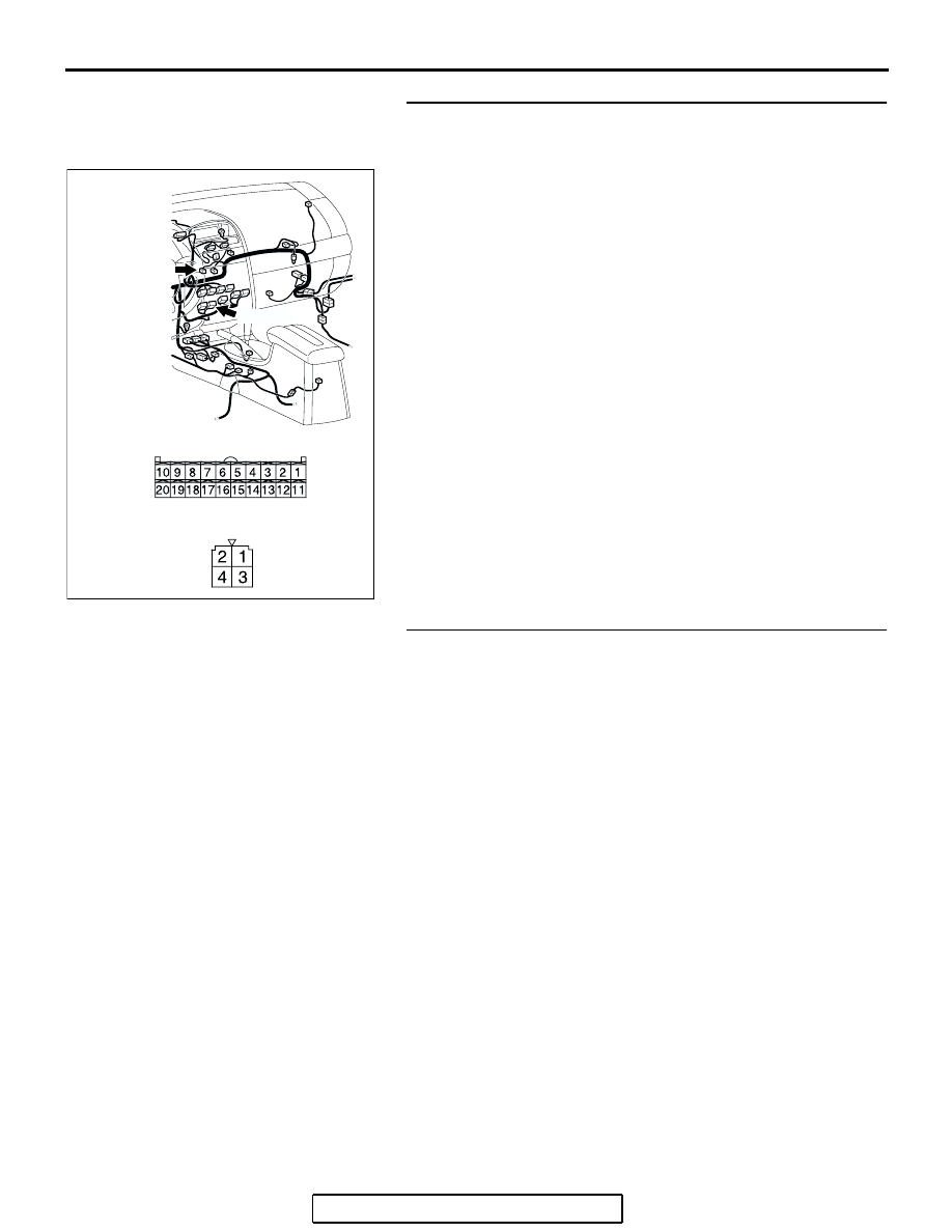
STEP 7. Check the wiring harness between power 
transistor connector C-104 (terminals 1 and 3) and 
A/C-ECU connector C-15 (terminals 17 and 18).
Q: Are the wiring harness between power transistor 

connector C-104 (terminals 1 and 3) and A/C-ECU 
connector C-15 (terminals 17 and 18) in good condition?
YES : 
 Go to Step 8.
NO :  Repair the wiring harness. The blower motor should 

operate normally.

STEP 8. Replace the power transistor.
Q: Does the blower motor operate normally?

YES : It can be assumed that this malfunction is intermittent. 

Refer to GROUP 00, How to Use 
Troubleshooting/Inspection Service Points 

− How to 

Cope with Intermittent Malfunctions 

P.00-14

.

NO :  Replace the A/C-ECU. Check that the air conditioning 

works normally. 

AC305234

C-104

HARNESS SIDE

C-104

HARNESS SIDE

C-15

AT

CONNECTORS: C-15, C-104

C-15 (B)

MANUAL A/C DIAGNOSIS

TSB Revision

HEATER, AIR CONDITIONING AND VENTILATION

55A-221

INSPECTION PROCEDURE 7: The A/C Indicator Flashes.

.

TECHNICAL DESCRIPTION (COMMENT)

If the A/C indicator flashes, inadequate refrigerant 
quantity, the ambient air temperature sensor circuit 
or the A/C pressure sensor circuit is suspected.

.

TROUBLESHOOTING HINTS

• Malfunction of the A/C pressure sensor

• Malfunction of the ambient air temperature sen-

sor

• Malfunction of the A/C-ECU

A/C-ECU

A/C PRESSURE
SENSOR

A/C Pressure Sensor Circuit

AC305206

A-30 (B)

AZ

CONNECTOR: A-30

AC305233

C-16 (B)

C-15 (B)

CONNECTORS: C-15, C-16

BE

AC305231

CONNECTOR: C-29

AH

MANUAL A/C DIAGNOSIS

TSB Revision

HEATER, AIR CONDITIONING AND VENTILATION

55A-222

DIAGNOSIS

Required Special Tools:

• MB991223: Test Harness Set

•  MB991958: Scan Tool (MUT-III Sub Assembly)

• MB991824: Vehicle Communication Interface (V.C.I.)

• MB991827: MUT-III USB Cable

• MB991910: MUT-III Main Harness A (Vehicles with CAN 

communication system)

STEP 1. Using scan tool MB991958, read the diagnostic 
trouble code.
Check if an A/C-ECU DTC is set.
(1) Connect scan tool MB991958 to the data link connector.
(2) Turn the ignition switch to the "ON" position.
(3) Check if the DTC is set.
(4) Turn the ignition switch to the "LOCK" (OFF) position.
Q: Is the check result satisfactory?

YES : Go to Step 2.
NO :  Refer to DIAGNOSTIC TROUBLE CODE CHART 

P.55A-58

.

AC206894

AB

MB991910

DATA LINK

CONNECTOR

MB991824

MB991827

MANUAL A/C DIAGNOSIS

TSB Revision

HEATER, AIR CONDITIONING AND VENTILATION

55A-223

STEP 2. Using scan tool MB991958, check data list item 04: 
A/C pressure sensor.

CAUTION

To prevent damage to scan tool MB991958, always turn the 
ignition switch to the "LOCK" (OFF) position before con-
necting or disconnecting scan tool MB991958.
(1) Connect scan tool MB991958 to the data link connector.
(2) Assemble a manifold gauge onto the high pressure service 

valve.

(3) Turn ON the engine and then turn ON the air conditioner 

switch.

(4) Set scan tool MB991958 to the data reading mode for item 

04: A/C pressure sensor.

• Check that the refrigerant pressure matches the dis-

played value on the scan tool.

(5) Turn the ignition switch to the "LOCK" (OFF) position.
Q: Is the sensor within the specified range?

YES : Go to Step 7.
NO :  Go to Step 3.

AC305412

AB

MB991910

DATA LINK

CONNECTOR

MB991824

MB991827


Content   ..  284  285  286  287   ..