Mitsubishi Galant 9G. Manual - part 282


  Index      Mitsubishi     Mitsubishi Galant 9G - service repair manual


Search            


Content   ..  280  281  282  283   ..


Mitsubishi Galant 9G. Manual - part 282


MANUAL A/C DIAGNOSIS

TSB Revision

HEATER, AIR CONDITIONING AND VENTILATION

55A-204

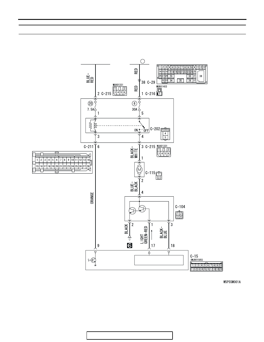
INSPECTION PROCEDURE 5: Front Blower Fan and Motor do not Turn.

IGNITION 
SWITCH (IG2)

FUSIBLE
LINK

1

JUNCTION
BLOCK

BLOWER
RELAY

BLOWER
MOTOR

A/C-ECU

POWER TRANSISTOR
DRIVE CIRCUIT

POWER
TRANSISTOR

Blower Motor Circuit

MANUAL A/C DIAGNOSIS

TSB Revision

HEATER, AIR CONDITIONING AND VENTILATION

55A-205

.

CIRCUIT OPERATION

If the blower motor does not operate, the blower 
relay system is suspected.

.

TROUBLESHOOTING HINTS

• Malfunction of the front blower relay

• Malfunction of the power transistor

• Malfunction of the front blower motor

• Malfunction of the A/C-ECU

• Damaged harness wires or connectors

AC305015AH

FUSIBLE LINK (1)

FUSIBLE LINKS 
NO.1

AC305233BP

CONNECTORS: C-14, C-115

C-14

C-115

AC305231

CONNECTOR: C-29

AH

AC305415BD

CONNECTORS: C-202, C-211, C-215, C-216

JUNCTION BLOCK 
(FRONT VIEW)

C-216 (B)

C-215

C-202

C-211

MANUAL A/C DIAGNOSIS

TSB Revision

HEATER, AIR CONDITIONING AND VENTILATION

55A-206

DIAGNOSIS

Required Special Tool:

• MB991223: Test Harness Set

STEP 1. Check blower motor connector C-115 and 
A/C-ECU connector C-15 for loose, corroded or damaged 
terminals, or terminals pushed back in the connector.
Q: Are blower motor connector C-115 and A/C-ECU 

connector C-15 in good condition?
YES : 
Go to Step 2.
NO :  Repair or replace the connector. Refer to GROUP 

00E, Harness Connector Inspection 

P.00E-2

.The 

blower motor should operate normally.

AC305234

CONNECTORS: C-15, C-115

HARNESS SIDE

C-15

C-115

HARNESS SIDE

C-115

C-15 (B)

AQ

MANUAL A/C DIAGNOSIS

TSB Revision

HEATER, AIR CONDITIONING AND VENTILATION

55A-207

STEP 2. Measure the voltage at blower motor connector 
C-115. 
(1) Disconnect blower motor connector C-115, and measure 

the voltage at the wiring harness side.

(2) Disconnect A/C-ECU connector C-15 and ground harness 

side terminal No.9.

(3) Turn the ignition switch to the "ON" position.

(4) Measure the voltage between terminal 1 and ground.

• The measured value should be approx. 12 volts (battery 

positive voltage).

Q: Is the measured voltage approx. 12 volts?

YES :  Go to Step 11.
NO :   Go to Step 3.

STEP 3. Check blower relay connector C-202 for loose, 
corroded or damaged terminals, or terminals pushed back 
in the connector.
Q: Is blower relay connector C-202 in good condition?

YES : Go to Step 4.
NO :  Repair or replace the connector. Refer to GROUP 

00E, Harness Connector Inspection 

P.00E-2

.The 

blower motor should operate normally.

AC305233BN

CONNECTOR: C-115

HARNESS SIDE

AC306911

AC306911AB

CONNECTOR C-15 
(HARNESS SIDE)

AC209365

CONNECTOR C-115 
(HARNESS SIDE)

GW

AC305415BC

CONNECTOR: C-202

JUNCTION BLOCK SIDE

JUNCTION BLOCK 
(FRONT VIEW)


Content   ..  280  281  282  283   ..