Mitsubishi Galant 9G. Manual - part 247


  Index      Mitsubishi     Mitsubishi Galant 9G - service repair manual


Search            


Content   ..  245  246  247  248   ..


Mitsubishi Galant 9G. Manual - part 247


MANUAL A/C DIAGNOSIS

TSB Revision

HEATER, AIR CONDITIONING AND VENTILATION

55A-64

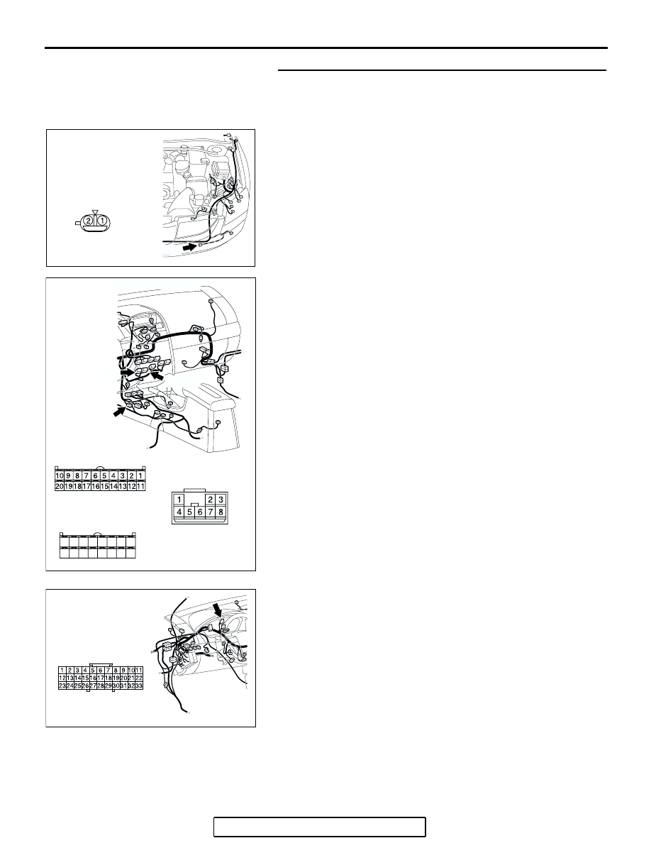
STEP 7. Check the wiring harness between A/C-ECU 
connector C-15 (terminal 20), C-16 (terminal 23) and 
ambient air temperature sensor connector A-25 (terminals 
1 and 2).

NOTE: Also check intermediate connector C-23 and joint con-
nector C-03 for loose, corroded, or damaged terminals, or ter-
minals pushed back in the connector. If intermediate connector 
C-23 or joint connector C-03 is damaged, repair or replace the 
connector as described in GROUP 00E, Harness Connector 
Inspection 

P.00E-2

.

Q: Are the wiring harness between A/C-ECU connector 

C-15 (terminal 20), C-16 (terminal 23) and ambient air 
temperature sensor connector A-25 (terminals 1 and 2) 
in good condition?
YES : 
Replace the A/C-ECU. Then go to Step 8.
NO :  Repair the wiring harness. Then go to Step 8.

AC305210

A-25 (BR)

HARNESS SIDE

CONNECTOR: A-25

AP

AC305234

HARNESS SIDE

C-16

C-15

HARNESS SIDE

21

22

23

24

25

26

27

28

29

30

31

32

33

34

35

36

C-15 

C-16 (B)

CONNECTORS: C-15, C-16, C-23

C-23

C-23

BH

AC305231BP

CONNECTOR: C-03

MANUAL A/C DIAGNOSIS

TSB Revision

HEATER, AIR CONDITIONING AND VENTILATION

55A-65

STEP 8. Recheck for diagnostic trouble code.
Check again if the DTC is set.
(1) Connect scan tool MB991958 to the data link connector
(2) Turn the ignition switch to the "ON" position.
(3) Check if the DTC is set.
(4) Turn the ignition switch to the "LOCK" (OFF) position.
Q: Is the check result satisfactory?

YES : The procedure is complete.
NO :  Return to Step 1.

DTC B1021, B1022: Air Thermo Sensor System

AC305412

AB

MB991910

DATA LINK

CONNECTOR

MB991824

MB991827

A/C-ECU

JOINT
CONNECTOR (2)

AIR THERMO
SENSOR

Air Thermo Sensor Circuit

MANUAL A/C DIAGNOSIS

TSB Revision

HEATER, AIR CONDITIONING AND VENTILATION

55A-66

.

DTC SET CONDITION

• DTC B1021 is set if there is a short circuit in the 

air thermo sensor input circuit.

• DTC B1022 is set if there is a defective connector 

connection, or if there is an open circuit in the 
harness.

.

TECHNICAL DESCRIPTION (COMMENT)

Current trouble

• The A/C-ECU, the air thermo sensor, or connec-

tor(s) or wiring between the two may be defec-
tive.

Past trouble

• If DTC B1021 or B1022 is stored as a past trou-

ble, carry out diagnosis with particular emphasis 
on wiring and connector(s) between the A/C-ECU 
and the air thermo sensor. If the connectors and 
wiring are normal, and obviously the ECU is the 
cause of the trouble, replace the ECU. If in doubt, 
do not replace the ECU.

TROUBLESHOOTING HINT

• Malfunction of connector.

• Malfunction of the harness.

• Malfunction of the air thermo sensor.

• Malfunction of the A/C-ECU.

AC305233

C-16 (B)

C-15 (B)

CONNECTORS: C-15, C-16

BE

AC305231

CONNECTOR: C-03, C-126

CC

C-126

C-03

MANUAL A/C DIAGNOSIS

TSB Revision

HEATER, AIR CONDITIONING AND VENTILATION

55A-67

DIAGNOSIS

Required Special Tool:

•  MB991958: Scan Tool (MUT-III Sub Assembly)

• MB991824: Vehicle Communication Interface (V.C.I.)

• MB991827: MUT-III USB Cable

• MB991910: MUT-III Main Harness A (Vehicles with CAN 

communication system)

STEP 1. Using scan tool MB991958, diagnose the CAN bus 
line.
Use scan tool MB991958 to diagnose the CAN bus lines.
(1) Connect scan tool MB991958 to the data link connector.
(2) Turn the ignition switch to "ON" position.
(3) Diagnose the CAN bus line.
Q: Is the check result satisfactory?

YES : Go to Step 2.
NO :  Repair the CAN bus lines. Repair the CAN bus lines 

(Refer to GROUP 54C, Diagnosis-Can Bus 
Diagnostic Chart 

P.54C-607

). Then go to Step 7.

STEP 2. Recheck for diagnostic trouble code.
Recheck if the DTC is set.
(1) Erase the DTC.
(2) Turn the ignition switch to "ON" position.
(3) Check if the DTC is set.
Q: Is the check result satisfactory?

YES : It can be assumed that this malfunction is intermittent. 

Refer to GROUP 00, How to Use 
Troubleshooting/Inspection Service Points 

− How to 

Cope with Intermittent Malfunctions 

P.00-14

.

NO :  Go to Step 3. 

AC305412

AB

MB991910

DATA LINK

CONNECTOR

MB991824

MB991827


Content   ..  245  246  247  248   ..