Mitsubishi Galant 9G. Manual - part 240


  Index      Mitsubishi     Mitsubishi Galant 9G - service repair manual


Search            


Content   ..  238  239  240  241   ..


Mitsubishi Galant 9G. Manual - part 240


MANUAL A/C DIAGNOSIS

TSB Revision

HEATER, AIR CONDITIONING AND VENTILATION

55A-36

DIAGNOSIS

Required Special Tool:

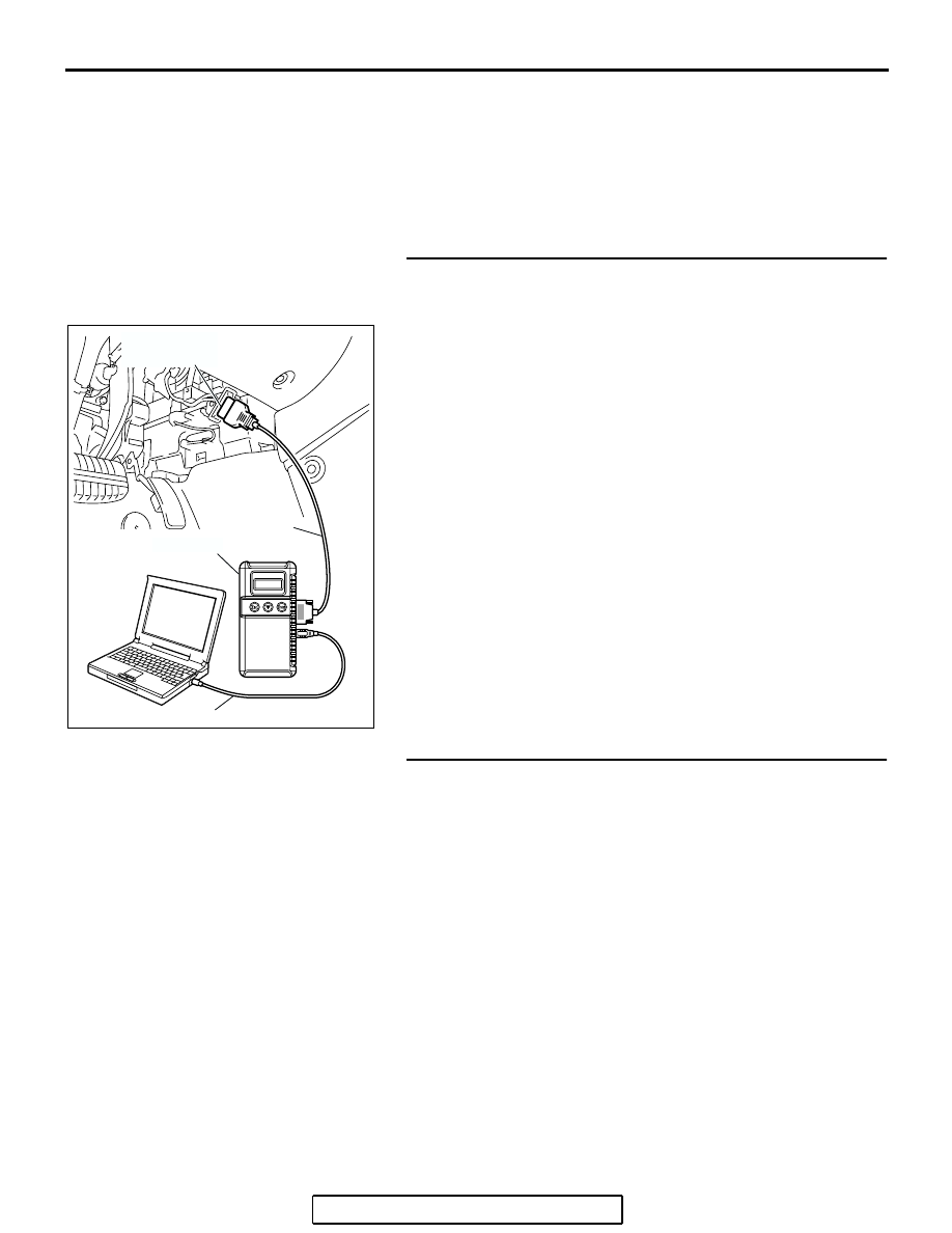
•  MB991958: Scan Tool (MUT-III Sub Assembly)

• MB991824: Vehicle Communication Interface (V.C.I.)

• MB991827: MUT-III USB Cable

• MB991910: MUT-III Main Harness A (Vehicles with CAN 

communication system)

STEP 1. Using scan tool MB991958, diagnose the CAN bus 
line.
Use scan tool MB991958 to diagnose the CAN bus lines.
(1) Connect scan tool MB991958 to the data link connector.
(2) Turn the ignition switch to "ON" position.
(3) Diagnose the CAN bus line.
Q: Is the check result satisfactory?

YES : Go to Step 2.
NO :  Repair the CAN bus lines. (Refer to GROUP 54C, 

Diagnosis-Can Bus Diagnostic Chart 

P.54C-607

). 

Then go to Step 7.

STEP 2. Recheck for diagnostic trouble code.
Recheck if the DTC is set.
(1) Erase the DTC.
(2) Turn the ignition switch to "ON" position.
(3) Check if the DTC is set.
Q: Is the check result satisfactory?

YES : It can be assumed that this malfunction is intermittent. 

Refer to GROUP 00, How to Use 
Troubleshooting/Inspection Service Points 

− How to 

Cope with Intermittent Malfunctions 

P.00-14

.

NO :  Go to Step 3. 

AC305412

AB

MB991910

DATA LINK

CONNECTOR

MB991824

MB991827

MANUAL A/C DIAGNOSIS

TSB Revision

HEATER, AIR CONDITIONING AND VENTILATION

55A-37

STEP 3. Using scan tool MB991958, check data list item 12: 
Air outlet c/o potentiometer.

CAUTION

To prevent damage to scan tool MB991958, always turn the 
ignition switch to the "LOCK" (OFF) position before con-
necting or disconnecting scan tool MB991958.
(1) Connect scan tool MB991958 to the data link connector.
(2) Start the engine.
(3) Set scan tool MB991958 to the data reading mode for item 

12: Air outlet c/o potentiometer.

• Check that the set position of the heater control matches 

the displayed position on the scan tool.

(4) Turn the ignition switch to the "LOCK" (OFF) position.
Q: Is the sensor within the specified range?

YES : Replace the A/C-ECU. Then go to Step 7.
NO :  Go to Step 4.

STEP 4. Check A/C-ECU connector C-10 and mode 
selection damper control motor and potentiometer 
connector C-102 for loose, corroded or damaged 
terminals, or terminals pushed back in the connector.
Q: Are A/C-ECU connectors C-10 and mode selection 

damper control motor and potentiometer connector 
C-102 in good condition?
YES : 
Go to Step 5.
NO :  Repair or replace the connector. Refer to GROUP 

00E, Harness Connector Inspection 

P.00E-2

. Then go 

to Step 7.

AC305412

AB

MB991910

DATA LINK

CONNECTOR

MB991824

MB991827

AC305233AW

CONNECTOR: C-10

HARNESS SIDE

C-10 (B)

AC305231

C-102

HARNESS SIDE

CD

CONNECTOR: C-102

MANUAL A/C DIAGNOSIS

TSB Revision

HEATER, AIR CONDITIONING AND VENTILATION

55A-38

STEP 5. Check the wiring harness between A/C-ECU 
connectors C-10 (terminals 15, 11 and 10) and mode 
selection damper control motor and potentiometer 
connector C-102 (terminals 5, 7 and 3).

NOTE: Also check joint connector C-03 for loose, corroded, or 
damaged terminals, or terminals pushed back in the connector. 
If joint connector C-03 is damaged, repair or replace the con-
nector as described in GROUP 00E, Harness Connector 
Inspection 

P.00E-2

.

Q: Are the wiring harnesses between A/C-ECU connectors 

C-10 (terminals 15, 11 and 10) and mode selection 
damper control motor and potentiometer connector 
C-102 (terminals 5, 7 and 3) in good condition?
YES : 
Go to Step 6.
NO :  Repair the wiring harness. Then go to Step 7.

AC305233AW

CONNECTOR: C-10

HARNESS SIDE

C-10 (B)

AC305232

C-03

C-102

CONNECTORS: C-03, C-102

HARNESS SIDE

C-102

C-03

AR

MANUAL A/C DIAGNOSIS

TSB Revision

HEATER, AIR CONDITIONING AND VENTILATION

55A-39

STEP 6. Check the mode selection damper control motor 
and potentiometer.

CAUTION

Do not apply battery voltage when the damper is in the 
FACE or DEF position.
(1) Operate the mode selection damper control motor as 

described in the table below.

(2) Measure the resistances between connector terminals 3 

and 5, and between 3 and 7, while the mode selection 
damper control motor is running. The resistances should 
change gradually within the standard value.

Standard value: 0.8 (DEF) 

 4.8 (FACE) k

Q: Are the mode selection damper control motor and 

potentiometer in good condition?
YES : 
Replace the A/C-ECU. Then go to Step 7.
NO :  Replace the mode selection damper control motor 

and potentiometer. Then go to Step 7.

LEVER POSITION BATTERY 

CONNECTION

LEVER 
OPERATION

At the FACE 
position

• Connect 

terminal 2 to the 
positive battery 
terminal

• Connect 

terminal 1 to the 
negative battery 
terminal

The lever moves 
from the FACE 
position to the DEF 
position

At the DEF position

• Connect 

terminal 1 to the 
positive battery 
terminal

• Connect 

terminal 2 to the 
negative battery 
terminal

The lever moves 
from the DEF 
position to the 
FACE position

AC209789

FACE POSITION

DEF POSITION

AB

1 2

4

3

5

7

6


Content   ..  238  239  240  241   ..