Mitsubishi Galant 9G. Manual - part 1614


  Index      Mitsubishi     Mitsubishi Galant 9G - service repair manual


Search            


Content   ..  1612  1613  1614  1615   ..


Mitsubishi Galant 9G. Manual - part 1614


ANTI-LOCK BRAKING SYSTEM (ABS) DIAGNOSIS

TSB Revision

ANTI-LOCK BRAKING SYSTEM (ABS)

35B-40

ABS DTC  SET CONDITIONS

These diagnostic trouble codes will be set under the 
cases below.

• The solenoid valve is not energized even after 

the ABS-ECU has turned on the driving transistor 
(Open circuit is present in the power supply cir-
cuit to the ABS-ECU solenoid valve, or the valve 
relay has failed).

• The solenoid valve is not energized even after 

the ABS-ECU has turned on the driving transistor 
(Open circuit is present in the solenoid valve cir-
cuit inside the ABS-ECU, or the valve relay has 
failed).

• After the ABS-ECU has turned off the driving 

transistor, the solenoid valve still remains ener-
gized (short in the solenoid valve circuit).

• When a solenoid valve failure is detected

.

TROUBLESHOOTING HINTS (The most 
likely causes for these DTCs are to set 
are:)

Current trouble

• Damaged wiring harness or connector

• Malfunction of the hydraulic unit (integrated with 

ABS-ECU)

.

Past trouble

• Carry out diagnosis with particular emphasis on 

connector(s) or wiring harness between the 
power supply circuit (terminal 1) to the ABS-ECU 
solenoid valve or ground circuit (terminal 2) . For 
diagnosis procedures, refer to "How to cope with 
past trouble" (Refer to GROUP 00, How to Use 
Troubleshooting/Inspection Service Points 

P.00-16

).

.

DIAGNOSIS

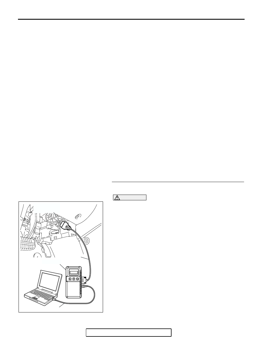
Required Special Tools:

• MB991958: Scan Tool (MUT-III Sub Assembly)

• MB991824: Vehicle Communication Interface (V.C.I.)

• MB991827: MUT-III USB Cable

• MB991910: MUT-III Main Harness A

• MB991970: ABS Check Harness

STEP 1. Using scan tool MB991958, diagnose the CAN bus 
line.

CAUTION

To prevent damage to scan tool MB991958, always turn the 
ignition switch to the "LOCK" (OFF) position before con-
necting or disconnecting scan tool MB991958.
(1) Connect scan tool MB991958 to the data link connector.
(2) Turn the ignition switch to the "ON" position.
(3) Diagnose the CAN bus line.
(4) Turn the ignition switch to the "LOCK" (OFF) position.
Q: Is the CAN bus line found to be normal?

YES : Go to Step 3.
NO :  Repair the CAN bus line (Refer to GROUP 54C, 

Diagnosis 

P.54C-14

).  Then go to Step 2.

AC305412

AB

MB991910

DATA LINK

CONNECTOR

MB991824

MB991827

ANTI-LOCK BRAKING SYSTEM (ABS) DIAGNOSIS

TSB Revision

ANTI-LOCK BRAKING SYSTEM (ABS)

35B-41

STEP 2. Recheck for diagnostic trouble code.

CAUTION

To prevent damage to scan tool MB991958, always turn the 
ignition switch to the "LOCK" (OFF) position before con-
necting or disconnecting scan tool MB991958.
(1) Erase the DTC.
(2) Turn the ignition switch to the "ON" position.
(3) Check if the DTC is set.
(4) Turn the ignition switch to the "LOCK" (OFF) position.
Q: Is DTC C1226, C1231, C1236, C1241, C1246, C1251, 

C1256 or C1261 set?
YES : 
Go to Step 3.
NO :  The procedure is complete.

AC305412

AB

MB991910

DATA LINK

CONNECTOR

MB991824

MB991827

ANTI-LOCK BRAKING SYSTEM (ABS) DIAGNOSIS

TSB Revision

ANTI-LOCK BRAKING SYSTEM (ABS)

35B-42

STEP 3. Measure the voltage at ABS-ECU connector A-02.
(1) Disconnect the connector A-02, and connect special tool 

ABS Check Harness (MB991970) to the wiring 
harness-side connector.
NOTE: Do not connect special tool ABS Check Harness 
(MB991970) to the ABS-ECU.

(2) Turn the ignition switch to the "ON" position.
(3) Measure the voltage between terminal 1 and ground. It 

should be approximately 12 volts (battery positive voltage).

Q: Is the voltage approximately 12 volts (battery positive 

voltage)?
YES : 
Go to Step 5.
NO :  Go to Step 4.

AC306403

19

2

18

1

8

9

7

6

5

4

3

10

11   

25

15

16

17

27

28

26

12

13

14

23

24

22 21 20

AE

ABS-ECU

MB991970

CHECK CONNECTOR

A-02 HARNESS
 CONNECTOR

A-02 (GR)

CONNECTOR: A-02

HYDRAULIC UNIT
(WITH BUILT-IN ABS-ECU)

ANTI-LOCK BRAKING SYSTEM (ABS) DIAGNOSIS

TSB Revision

ANTI-LOCK BRAKING SYSTEM (ABS)

35B-43

STEP 4. Check ABS-ECU connector A-02  for loose, 
corroded or damaged terminals, or terminals pushed back 
in the connector.
Q: Is ABS-ECU connector A-02 damaged?

YES : Repair or replace the damaged component(s). Refer 

to GROUP 00E, Harness Connector Inspection 

P.00E-2

. Then go to Step 8.

NO :  An open or short circuit may be present in the 

solenoid valve power supply circuit. Repair the wiring 
harness between ABS-ECU connector A-02 terminal 
1 and fusible link No.3.Then go to Step 8.

AC306406

19

2

18

1

8

9

7

6

5

4

3

10

11   

25

15

16

17

27

28

26

12

13

14

23

24

22 21 20

A-02 HARNESS CONNECTOR
(HARNESS SIDE)

AB

A-02 (GR)

CONNECTOR: A-02

HYDRAULIC UNIT
(WITH BUILT-IN ABS-ECU)


Content   ..  1612  1613  1614  1615   ..