Mitsubishi Galant 9G. Manual - part 1595


  Index      Mitsubishi     Mitsubishi Galant 9G - service repair manual


Search            


Content   ..  1593  1594  1595  1596   ..


Mitsubishi Galant 9G. Manual - part 1595


MULTI-CENTER DISPLAY

TSB Revision

CHASSIS ELECTRICAL

54A-252

SYMPTOM PROCEDURES

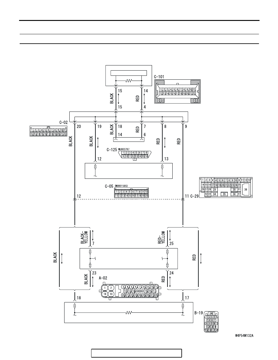
INSPECTION PROCEDURE 1:Communication With Scan Tool Is Not Possible. (Middle Grade Type)

WITHOUT ELECTRONIC 
BRAKE-FORCE 
DISTRIBUTION (EBD) 
AND ANTI-LOCK 
BRAKING SYSTEM 
(ABS)

WITHOUT ELECTRONIC 
BRAKE-FORCE 
DISTRIBUTION (EBD) 
AND ANTI-LOCK 
BRAKING SYSTEM 
(ABS)

WITH ELECTRONIC 
BRAKE-FORCE 
DISTRIBUTION (EBD) 
AND ANTI-LOCK 
BRAKING SYSTEM 
(ABS)

WITH ELECTRONIC 
BRAKE-FORCE 
DISTRIBUTION (EBD) 
AND ANTI-LOCK 
BRAKING SYSTEM 
(ABS)

ABS-ECU OR ABS/TCL-ECU

JOINT 
CONNECTOR (3)

POWERTRAIN 
CONTROL MODULE

COMBINATION 
METER

MULTI-CENTER DISPLAY UNIT

DATA LINK CONNECTOR

CPU

Data LInk Connector Circuit

MULTI-CENTER DISPLAY

TSB Revision

CHASSIS ELECTRICAL

54A-253

.

CIRCUIT OPERATION

The multi-center display unit (middle grade type) is 
linked to CAN communication lines to communicate 
with the combination meter and the powertrain con-
trol module, both of which have a terminator resistor.

.

TECHNICAL DESCRIPTION (COMMENT)

If the system does not communicate with the scan 
tool, power supply to the data link connector or CAN 
bus lines may be defective.

.

TROUBLESHOOTING HINTS

• The wiring harness or connectors may have 

loose, corroded, or damaged terminals, or termi-
nals pushed back in the connector.

AC305206

CONNECTOR: A-02

AO

A-02 (GR)

AC305216

B-19 (B)

CONNECTOR: B-19

AD

AC305233

C-05 (B)

CP

CONNECTOR: C-05

AC305231

C-02

C-29

C-101

C-125 (B)

DC

CONNECTORS: C-02, C-29, C-101, C-125

MULTI-CENTER DISPLAY

TSB Revision

CHASSIS ELECTRICAL

54A-254

DIAGNOSIS

Required Special Tools:

• MB991958: Scan Tool (MUT-III Sub Assembly)

• MB991824: Vehicle Communication Interface (V.C.I.)

• MB991827: MUT-III USB Cable

• MB991911: MUT-III Main Harness A (Vehicles with CAN 

communication system)

STEP 1. Check that the powertrain control module 
communicates with the scan tool.
Check if scan tool MB991958I can communicate with the 
multi-center display.
(1) Connect scan tool MB991958 to the data link connector.
(2) Turn the ignition switch to "ON" position.
(3) Check if scan tool MB991958 can communicate with the 

powertrain control module.

Q: Is the check result satisfactory?

YES : Go to Step 2.
NO :  Refer to GROUP 13A, MFI Diagnostic Trouble Code 

Chart 

P.13A-33

 or GROUP 13B, MFI Diagnostic 

Trouble Code Chart 

P.13B-34

.

STEP 2. Using scan tool MB991958, diagnose the CAN bus 
line
Use scan tool MB991958 to diagnose the CAN bus lines.
Q: Is the check result satisfactory?

YES : Diagnose the power supply circuit. Refer to 

P.54A-77

.

NO :  Repair the CAN bus lines (Refer to GROUP 54C, 

Diagnosis-Can Bus Diagnostic Chart 

P.54C-14

). 

AC305412

AB

MB991910

DATA LINK

CONNECTOR

MB991824

MB991827

MULTI-CENTER DISPLAY

TSB Revision

CHASSIS ELECTRICAL

54A-255

INSPECTION PROCEDURE 2: The multi-center display does not Show any Information. (Middle Grade 
type) 

JOINT 
CONNECTOR (2)

JOINT 
CONNECTOR (1)

JOINT 
CONNECTOR (2)

RELAY BOX

JUNCTION 
BLOCK

BATTERY

IGNITION 
SWITCH (ACC)

JOINT 
CONNECTOR (2)

POWER SUPPLY

MULTI-CENTER
DISPLAY UNIT

RELAY
BOX

IGNITION 
SWITCH (IG1)

Multi-Center Display Power Supply Circuit


Content   ..  1593  1594  1595  1596   ..